Mounting and Wiring VMA1400 Series Controllers Technical Bulletin
10
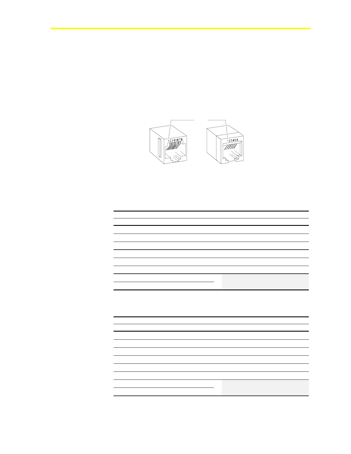
Phone Jack Polarization
Figure 2 illustrates the polarization of the 6-pin and 8-pin phone jacks
on the VMA or room sensor (TE-6700 or TMZ1600). Pin 1 is to the
extreme left as you face the jack opening, tab notch down.
Note: If you need to create your own cable, refer to Fabricating
Your Own Interconnection Cable in the Reference
Information section of this document. Otherwise, order
pre-terminated cables.
8-pin 6-pin
VMA
Room Sensor
phonejac
Pin 1
Figure 2: Phone Jack Polarization
Table 4: TE-6700 Phone Jack Pin Identification
8-Pin Phone Jack on VMA 6-Pin Phone Jack on TE-6700
Pin Signal Pin Signal
1
BI-1 Temp Occ
1
Not used
2
AI 2 Zone Setpoint
2
+15 VDC
3
AI 1 Temperature Sensor
3
COM
4
COM for AI-1
4
Not used
5
+15 VDC
5
Zone Bus (ZB)
6
ZB COM/LED BI COM
6
Not used
7
COM for AI-2
8
ZB+
Table 5: TMZ Phone Jack Pin Identification
8-Pin Phone Jack on TMZ 6-Pin Phone Jack on TMZ
Pin Signal Pin Signal
1
Not used
1
Not used
2
Not used
2
+15 VDC
3
AI1, Zone Temperature Sensor
3
COM
4
AI1, Sensor Common
4
Not used
5
+15 VDC
5
Zone Bus (ZB)
6
Supply/Zone Bus Common
6
Not used
7
Not used
8
Zone Bus

 Loading...


