Mounting and Wiring VMA1400 Series Controllers Technical Bulletin
19
Setting the Damper Position (VMA1410, 1420, or VMA1430 with
External Actuator)
To set the damper position:
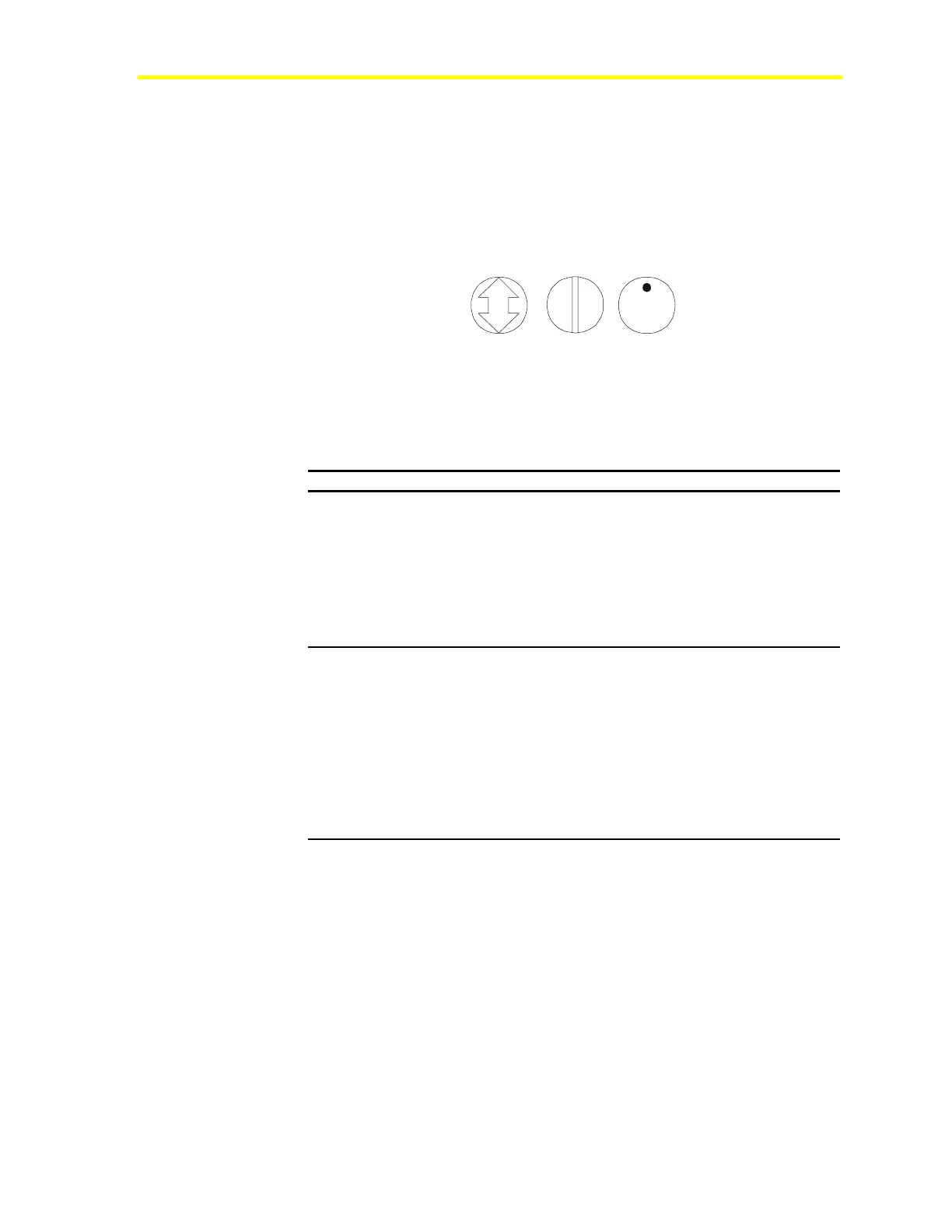
1. Locate the damper position, using the typical marking on the end
of the damper shaft (Figure 8). Note the direction, Clockwise
(CW) or Counterclockwise (CCW), required to close the damper.
DAMPOSIT
Figure 8: Typical Damper Shaft End Icons
2. Complete the steps described in Table 7. See Figure 9.
Table 7: Setting the Damper Position
Box Type Steps to Perform
90°
1. Grasp the damper shaft firmly with a pliers and manually
position it to fully closed (icon perpendicular to airflow).
2. Push down and hold the gear release lever and turn the VMA
coupler until it contacts the mechanical end stop at the fully
closed position. If the damper closes CCW, rotate the coupler
to the CCW mechanical limit. If the damper closes CW, rotate
the coupler to the CW mechanical limit. This provides a hard
stop for this position. The hard stop for the open position is
provided by the VMA.
45° or 60°
1. Grasp the damper shaft firmly with a pliers and manually
position it to fully open.
2. Push down and hold the gear release lever and turn the VMA
coupler until it contacts the mechanical end stop at the fully
open position.
Note: The open end stop is automatically set for 90° boxes.
Hard stops must be provided for 45° and 60° boxes at
both fully closed and fully open damper positions. By
installing the VMA at the fully open position, the VMA
provides the open stop for 45° and 60° boxes. The
closed damper seal provides the fully closed stop.

 Loading...


