Mounting and Wiring VMA1400 Series Controllers Technical Bulletin
29
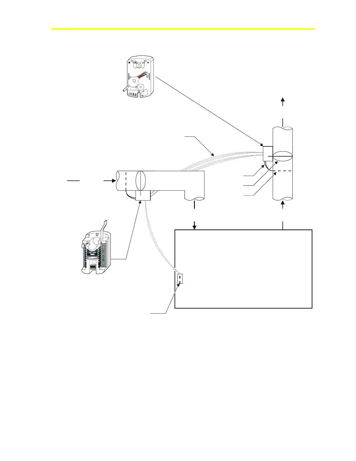
VMA Single Duct Supply/Exhaust Wiring Diagram
Zone
UP
(
-
)
L
O
D
P
T
-
2
0
1
5
O
U
T
G
N
D
I
N
Pressure Tubes
Damper
Flow Pickup
Connections to/from
Main Controller (VMA) to
Actuator/Sensor (M9104)
(See detail in Figure 17.)
Cold Air
from AHU
Supply Air
to Zone
Return Air
from Zone
Return to
Exhaust Fan
Zone Temperature Sensor to
VMA AI1 (26), COM (27)
AP - VMA1420-0
(Actuator, Pressure
Sensor, and Controller)
M9104-AGS-2N
(Actuator and Pressure Sensor)
sply_exhst
Figure 15: VMA Single Duct Supply/Exhaust Wiring Diagram

 Loading...


