Mounting and Wiring VMA1400 Series Controllers Technical Bulletin
34
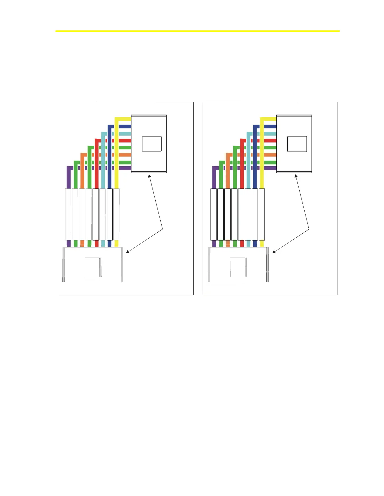
Fabricating Your Own Interconnection Cable
Construct any fabricated interconnection cable so the same color wire
on both ends of the cable aligns with Pin 1 in the plug. This provides a
consistent field assembly of the cable. Figure 20 illustrates the
interconnection cables for the TE-6700 and TMZ1600 sensors.
Cblfab_1
Phone
Connectors
(Clip Side Out)
TE-6700 Phone Plug
1234567
8
B
I
-
1
A
I
-
2
A
I
-
1
C
O
M
f
o
r
A
I
-
1
+
1
5
V
D
C
+
1
5
/
Z
B
/
L
E
D
-
B
I
C
O
M
C
O
M
f
o
r
A
I
-
2
Z
B
+
Controller
Phone
Plug
1
2
3
4
5
6
7
8
TE-6700 Room Sensor
TMZ1600 Phone Plug
1234567
8
N
o
t
U
s
e
d
N
o
t
U
s
e
d
A
I
-
1
A
I
C
O
M
+
1
5
V
D
C
+
1
5
C
O
M
N
o
t
U
s
e
d
Z
B
+
1
2
3
4
5
6
7
8
Controller
Phone
Plug
Phone
Connectors
(Clip Side Out)
TMZ1600 Room Sensor
Figure 20: TE-6700 and TMZ1600 Interconnection Cables
Note: This is not typical of preassembled phone cables purchased
in retail stores. A telephone system cable is wired opposite of
the Zone Sensor requirements.

 Loading...


