Mounting and Wiring VMA1400 Series Controllers Technical Bulletin
11
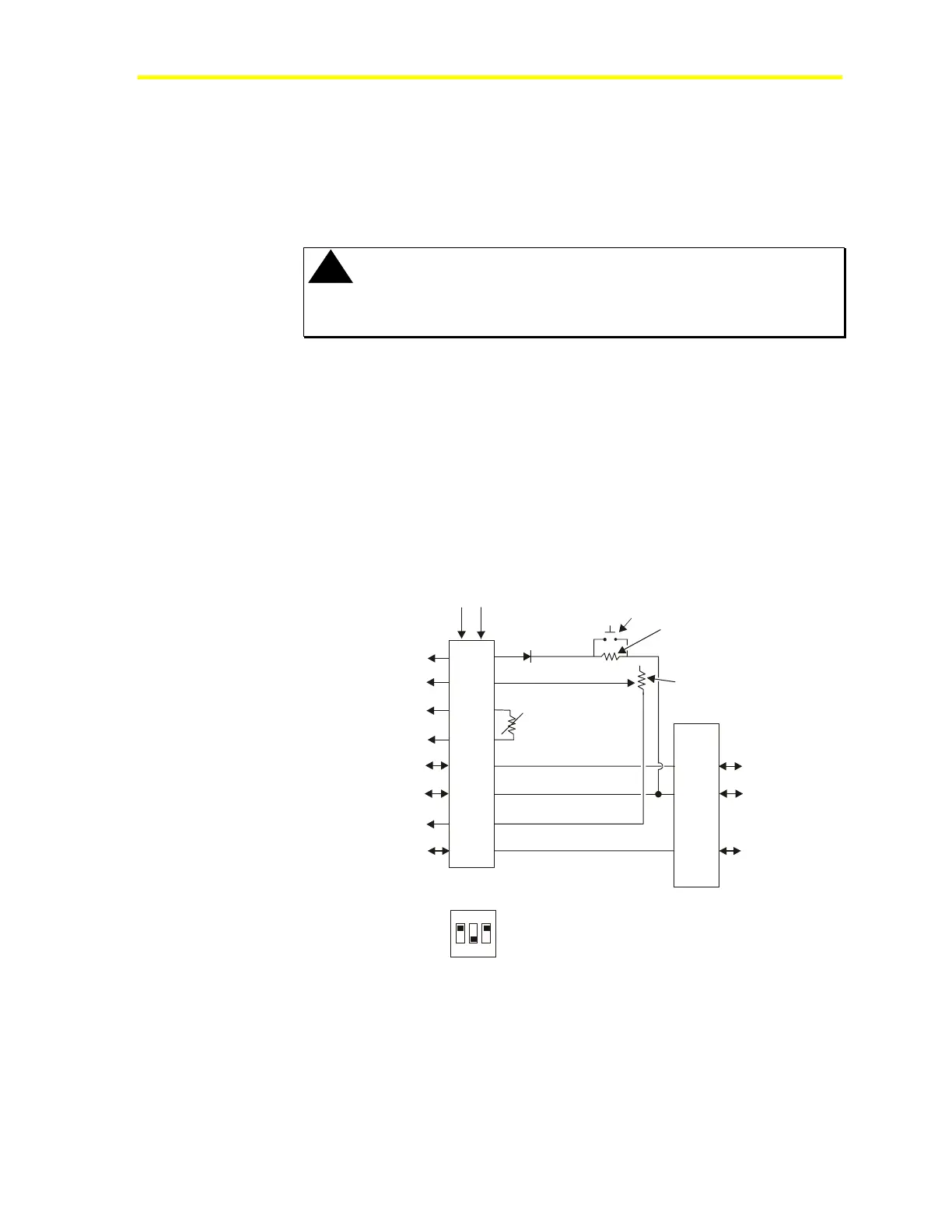
Sensor Interfaces
Figures 3, 4 and 5 show interfaces between room sensors and the
VMA. For more information on the TE-6700 room sensor (including
DIP switch settings), see the TE-6700 Series 2nd Generation
Temperature Elements Installation Bulletin (LIT-216332).
!
CAUTION: Intermittent connections can occur when small
gauge solid wire is crimped into large spade lugs
or a when a phone jack is poorly crimped.
Any of the following situations can cause AI drifting:
• 26 gauge solid wire is crimped in a 18-22 gauge stranded spade
connector.
• Phone jack is poorly crimped.
• Pliers or something other than crimping tool is used to crimp the
spade lug.
• Paint or other material is on phone jack connector.
See the Troubleshooting section for more information.
1
2
3
4
5
6
7
8
1
2
3
4
5
6
BI-1
AI-2 (Setpoint)
AI-1 (Zone Temperature)
AI-1 COM
+15 Volts DC
+15/Zone Bus COM (Not BCOM)
AI-2 COM
Zone Bus/N3+
Sensor
1.6 K ohm
Setpoint Potentiometer
6-pin Phone Jack
on TE-6700
+15 Volts DC
Zone Bus
COM
8-pin Phone Jack
on TE-6700
Screw
Termin als
TE6X
4
1
2
5
6
3
7
LED*
Manual
Override
1 K ohm
8
Preferred DIP Switch
Position for TE-6700 (LED On)
O N
1 2 3
*
Figure 3: TE-6700 Phone Jack Interface to VMA

 Loading...


