Mounting and Wiring VMA1400 Series Controllers Technical Bulletin
30
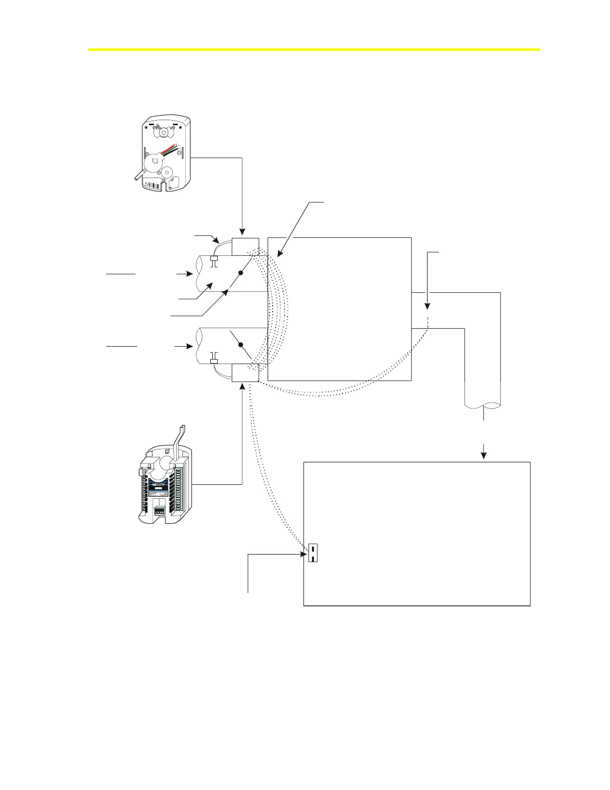
VMA Dual Duct Application Wiring Diagram
Figures 16 and 17 are wiring diagrams for dual duct applications.
M9104-AGS-2N
(Actuator and Pressure Sensor)
AP-VMA1420-0
(Actuator, Pressure
Sensor, and Controller)
Connections to/from
Main Controller (VMA) to
Actuator/Sensor (M9104)
(See detail in Figure 17.)
Cold Air
from AHU
Hot Air
from AHU
(Air Handling Unit)
Flow Pickup
Damper
Pressure Tubes
Discharge Air Temperature to
VMA AI4 (31), COM (32)
Zone Temperature Sensor to
VMA AI1 (26), COM (27)
Dual Duct
Mixing Box
Zone
Mixed Air
to Zone
dualductap
UP
(
-
)
L
O
D
P
T
-
2
0
1
5
O
U
T
G
N
D
I
N
Figure 16: VMA Dual Duct Wiring Diagram

 Loading...


