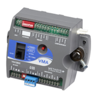
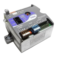
Mounting and Wiring VMA1400 Series Controllers Technical Bulletin
6
• Do not run N2 Bus, Zone Bus, Analog Input (AI), Binary Input
(BI), Analog Output (AO), or Binary Output (BO) wiring in the
same conduit as line voltage wiring (above 30 VAC), or with
wiring that switches power to highly inductive loads such as
contactors, coils, motors, or generators.
• Run Zone Bus, AI, AO, and BI wiring in the same bundle or
conduit where convenient. If the BO wiring is not wired through
other switches or contacts, such as actuator end-of-travel switches,
bundle it with the other Input/Output (I/O) wiring where
convenient.
General Wiring Information
The following are general wiring considerations:
• The VMA includes isolated N2, isolated binary outputs, and
isolated 24 VAC.
• The 24 VAC power input is internally transformer isolated by the
VMA. To meet NEC requirements for line voltage greater than
150 VAC, Terminal 1 can be earth grounded.
• Up to ten cooling-only controllers (VMA1410) can be powered
from one 100 VA low voltage power limited, Class 2 transformer.
See Power Source Wiring below for more information. Conduit is
not required by the NEC for Class 2 wiring installations.
• Large insulated spade lugs with a polarizing tab (for high voltage)
do not fit on the VMA.
Power Source Wiring
To calculate the number of VMAs that can be powered from
one 100 VA unit, use the equation below. In this equation, the value
TotalVA equals the total VA consumed by the VMA, actuator, and
output loads.
VA Total
100
r TransformeVA 100per VMAs =
Table 1 shows the power rating for each cooling/heating coil valve
actuator. The valve power plus the VMA power (1410/1420 = 10 VA;
1430 = 3 VA) must not exceed 100 VA. If a device is not listed in
Table 1, refer to the product literature for that device.
 Loading...

