EasyManuals Logo

Johnson Controls VMA1400 Series User Manual

Johnson Controls VMA1400 Series
38 pages
To Next Page IconTo Next Page
To Previous Page IconTo Previous Page
Page #32 background imageLoading...
Page #32 background image
Mounting and Wiring VMA1400 Series Controllers Technical Bulletin
32
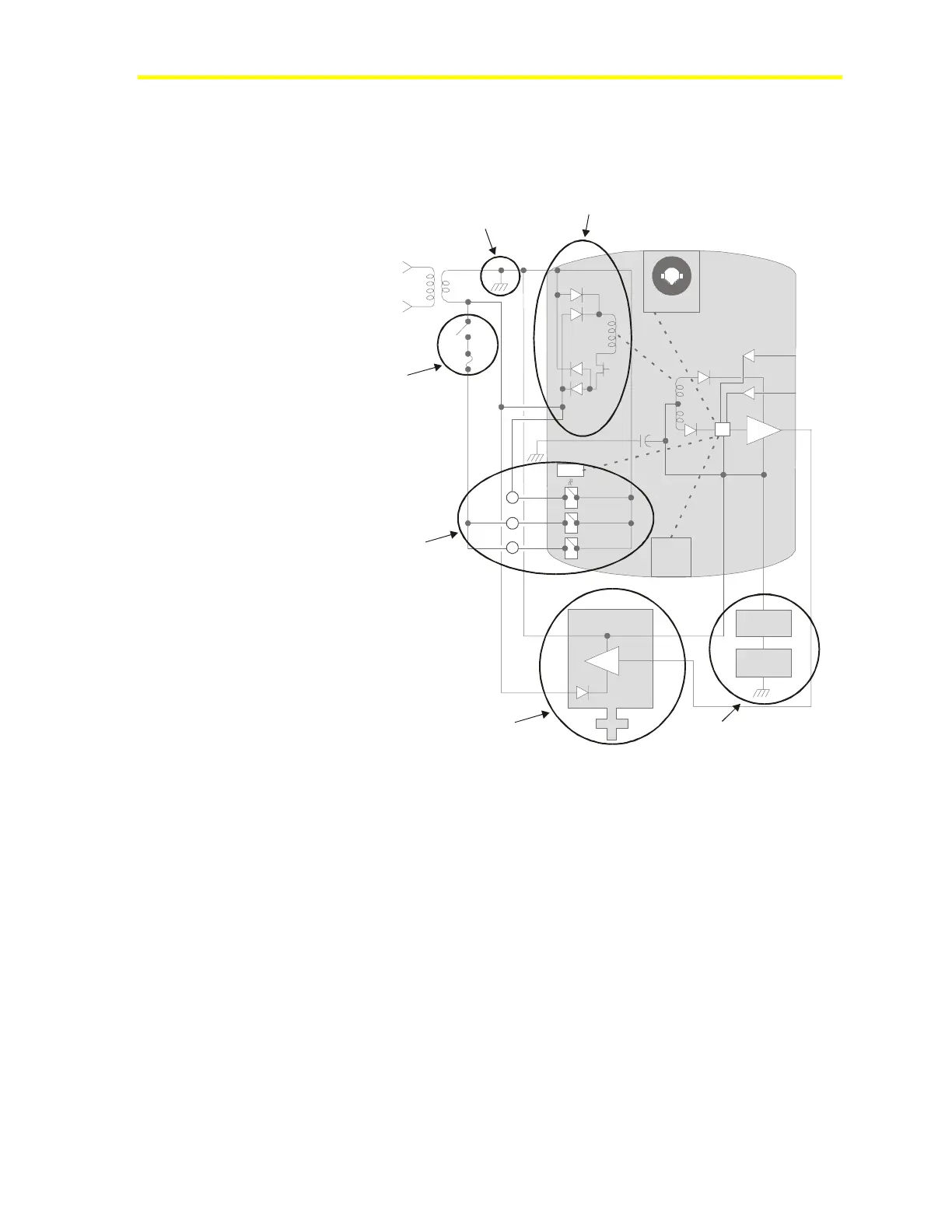
VMA Internal Schematic Diagram
The small diagram in Figure 18 is a key diagram showing the different
regions of the larger schematic diagram in Figure 19.
1. Isolated Power Supply
2. Earth Ground Connection
3. Airflow and
High Temperature
Safety Switches
4. Isolated Triacs
and Proper Wiring
5. Valve Actuators
6. Zone Bus
vmadia3
Figure 18: Key to Internal Schematic Diagram (Figure 19)

Questions and Answers:

Question and Answer IconNeed help?

Do you have a question about the Johnson Controls VMA1400 Series and is the answer not in the manual?

Johnson Controls VMA1400 Series Specifications

General IconGeneral
BrandJohnson Controls
ModelVMA1400 Series
CategoryController
LanguageEnglish

Related product manuals