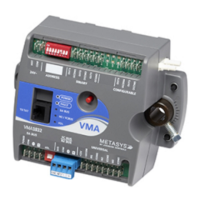
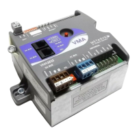
Mounting and Wiring VMA1400 Series Controllers Technical Bulletin
5
Wiring and Cabling Precautions
!
WARNING: Possible Equipment Damage or Electrical
Shock. To avoid damaging equipment or
possible electrical shock, ensure that all power
supplies to the system are disconnected prior to
wiring.
!
CAUTION: Shorting of Binary Outputs (BOs) while
energized will destroy the VMA output triac.
Read these precautions before touching the terminals or wiring the
VMA and its accessories:
• Make all wiring connections in accordance with the National
Electrical Code (NEC) and state and local regulations. For
transformer primaries above 150 VAC, the secondary must be
earth grounded at the transformer to meet NEC. Terminal 1 can be
earth grounded. Grounding on Terminal 1 results in 24 VAC being
applied to DCOM with respect to earth.
Note: 24 VAC to 24 VAC isolation transformers are not necessary.
The power supply is internally isolated. For specific methods
for wiring the VMA to meet Underwriters Laboratories, Inc.
(UL) 864 requirements, refer to the Metasys Smoke Control
Wiring Technical Bulletin (LIT-636331).
• Terminal 3 is an earth ground connection (optional).
• Locate equipment and route the wiring so that twisted pair signal
wiring is separated from power wiring by at least 150 mm (6 in.).
• Make all wiring connections to the VMA using only copper
conductors. To establish tight, reliable electrical connections, use
the correct wire sizes for the terminals. Avoid very thin solid
wires, such as 26 AWG or less than 0.6 mm, which tend to break.
• Daisy chain the N2 Bus. The use of Y or T connections without a
repeater installed as the T-tap may cause a loss of communications.
Make sure that there is at least one End-of-Line termination on the
N2 Bus (usually at the Network Control Module [NCM] or N30).
 Loading...

