Mounting and Wiring VMA1400 Series Controllers Technical Bulletin
15
To Do This (Cont.) Follow These Steps:
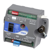
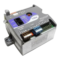
Wire the VMA
1. Disconnect all power to the VMA.
2. Determine if spade lugs, removable 2- or 3-position screw terminals,
or phone cable are to be used.
3. Terminate wiring per engineering drawings.
Connect the N2 Bus
1. Set the N2 address of the VMA per engineering drawings before
wiring the VMA (if not already done).
2. Connect the N2 Bus wires to the VMA, and continue in a daisy chain
to the next VMA. Repeat this process for each VMA.
3. Apply power. Locate and observe the VMA Light-Emitting Diode
(LED). If the LED is on solid, it is running a 20 second power up self
test. Continue. If the LED is blinking once per second, then it passed
diagnostics, but no N2 messages have been received for this VMA
address. Continue. If the LED is irregularly flashing about four times
every second, the supervisory system is polling the VMA.
 Loading...

