Mounting and Wiring VMA1400 Series Controllers Technical Bulletin
27
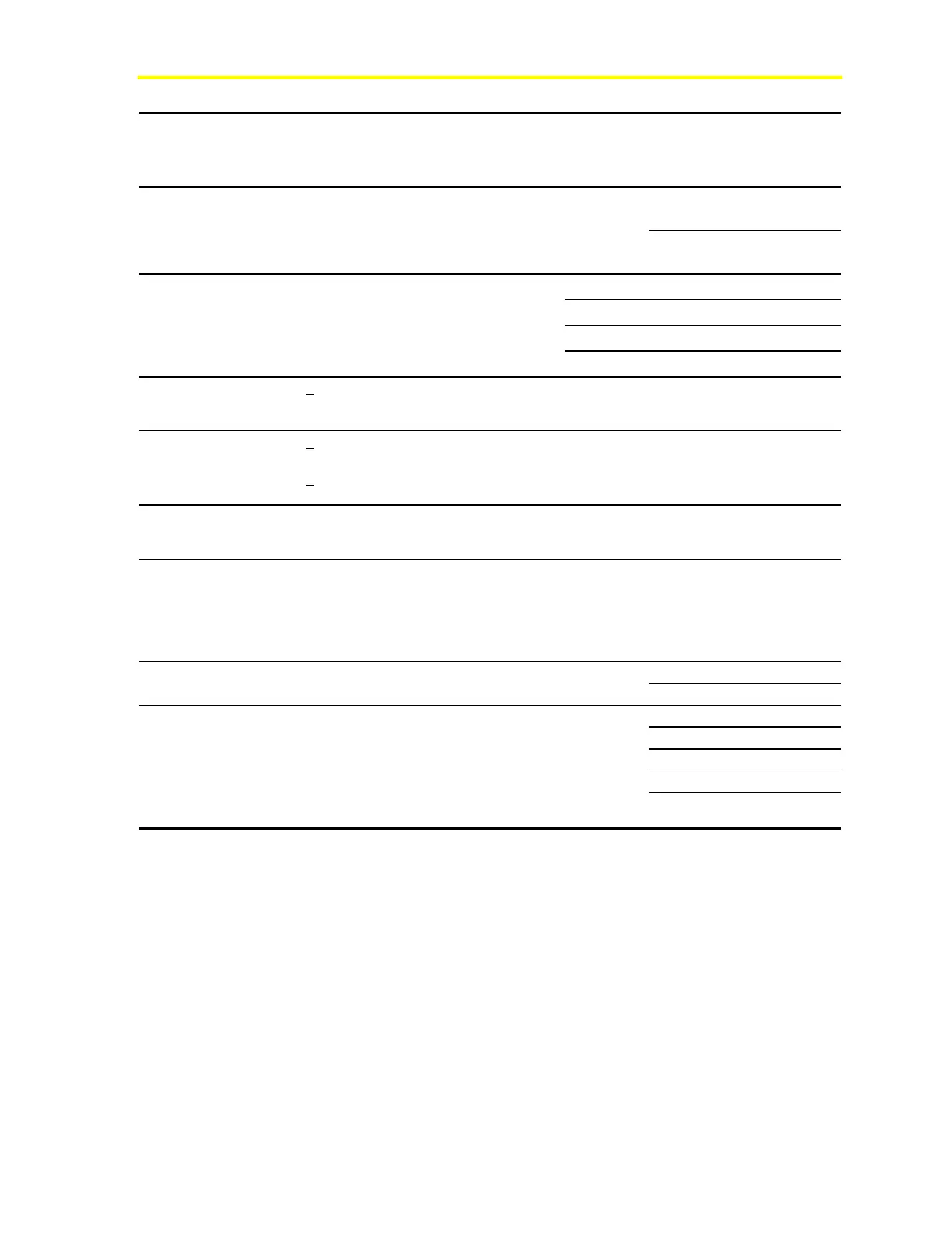
Point
(Cont.)
Description
or
Application
Range Input or
Load
Impedance
Maximum
Voltage
Maximum
Current
Wire Size in
mm
2
or mm
(AWG)
Cable
Length in
Meters
(ft)
1.5 mm
2
(18) 150 (500)
AO-2*
Proportional
Heat/
Humidity
Dpr. Actuator
Fan Speed
0-10 VDC 1K-10M ohm 10 VDC 10 mA
0.6 mm (24) 60 (200)
100 mA 1.5 mm
2
(18) 150 (500)
100 mA 0.6 mm (24) 30 (100)
500 mA 1.5 mm
2
(18) 30 (100)
BO-1,2,
3,4,5^
Fan
Box/
Supplemental
Heat
Electric Heat
Lighting
24 VAC @
25-500 mA
48-1000 ohm 30 VAC
500 mA 0.6 mm (24) 6 (20)
SM-1^
Stepper
motor
(internal)
+ 34 VDC
2-phase
72-100 ohm 40 VDC 250 mA NA Internal
N2
Bus*^
Networking
Bus
+ 5V
transmit,
+ 0.2V
receive
200 ohm line 5 VDC 100 mA 0.6 mm to
1.5 mm
2
(24 to 18)
1500
(5000)
Zone
Bus*
Local Room
Sensor Bus
0 to 5V or
±5V
>3000 ohm 5 VDC 100 mA 0.6 mm to
1.5 mm
2
(24 to 18)
150 (500)
Room
Sensor
Cable*
AI-1, AI-2,
BI-1, Zone
Bus, and
+15 VDC
See AI-1,
AI-2, BI-1,
Zone Bus,
and
+15 VDC in
this table.
0.6 mm (24)
eight conductor
phone cable
7.5 (25)
15 (50)
30 (100*)
1.5 mm
2
(18) 150 (500)
+15
VDC*
DC Output
Supply
13.5-
18 VDC
1K-10M ohm 18 VDC 35 mA
0.6 mm (24) 60 (200)
6 mm
2
(10) 67 (222)
4 mm
2
(12) 42 (140)
2.5 mm
2
(14) 27 (88)
1.5 mm
2
(16) 17 (55)
24
VAC^
Power
In
AC Supply
Voltage
20-30 VAC 12-48 ohm 30 VAC 417 mA for
1410/1420;
125 mA for
1430
(100 VA
cable
length)
1.5 mm
2
(18) 11 (35)
* Isolated from 24 VAC
^ Isolated from AI, BI, AO, Zone Bus, 15 VDC

 Loading...


