Mounting and Wiring VMA1400 Series Controllers Technical Bulletin
8
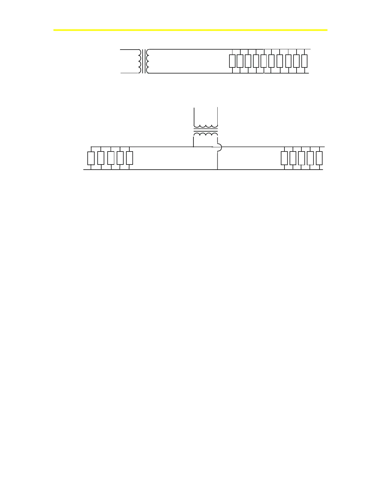
< 88 ft of 14 AWG >
24 VAC
< 176 ft of 14 AWG >
< 176 ft of 14 AWG >
100 VA
24 VAC
100 VA
VMA
VMA
VMA
VMA
VMA
VMA
VMA
VMA
VMA
VMA
VMA
VMA
VMA
VMA
Example 1: All ten VMAs are at one end.
Example 2: Transformer is centered.
VMA
VMA
VMA
VMA
VMA
VMA
Cable_lg
Figure 1: Power Cable Lengths
There are two ways to connect power and loads to the VMA.
Individual spade lugs accept a single 4 mm
2
to 0.8 mm
(10 to 22 AWG) wire and fit on 6 mm (1/4 in.) tabs, or optional screw
terminals can be assembled over the spade lugs. The screw terminals
accept up to a single 4 mm
2
(12 AWG) wire or two 2.5 mm
2
(14 AWG) wires. When two wires are crimped into one spade lug, a
wire nut (to connect two heavy wires to a short 152 mm [6 in.] thinner
wire) or a larger spade lug barrel is needed.

 Loading...


