(2) Instruction of HMI Interface
A0 B0 : Communication interface with
control board.
A1 B1 : Communication interface with
upper computer
V0 : Common ground end
Input the DC power of 10-24V, the end
marked with 0V is low, while the other end
is positive
Press for 1 minute, then loosen, the
centralized controller will be reset.
Note
ISP
10-24V
0V
A0 B0 A1 B1 0V
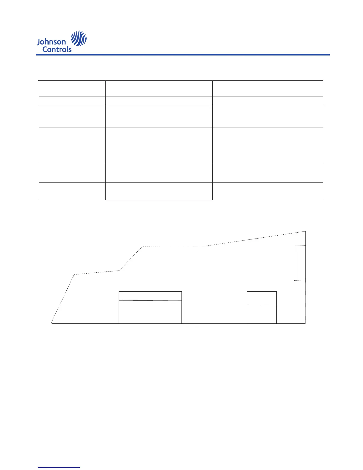
Wiring diagram of HMI
Instruction:
A0, B0: Communication interface of HMI and mainbord
A1, B1: Communication interface of HMI and upward computer
0-24V: Pwer connction of HMI, among which 0V means the ground.
ISP: Interface for downloading mainbord programs
Symbol
CN5(KEY BUS)
CN6(ISP)
CN2
CN3
RST_SW
Description
Keyboard interface
Download interface of ISP program
485 communication port
Input power
Reset key
YEWS-E Water Cooling Screw Chiller/Heat Pump
21

 Loading...


