(3) Instruction of Control board Interface
(4)Wiring diagram of control board
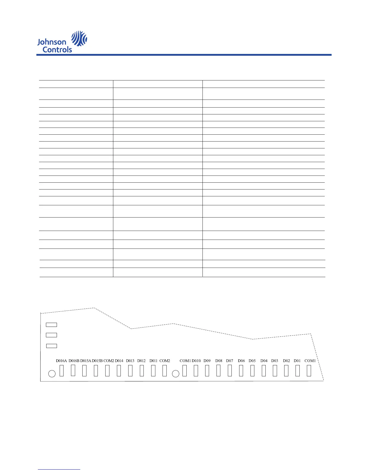
(a) Power and DO output interface diagram
Instruction
DO1-DO10 : Relay output
DO11-DO14 : Relay output
DO15A,DO15B : Bi-directional Thyristor output
L : AC220V live wire
N : Zero line
L
PE
N
Symbol
CON2(COMU)
COM
DI1–DI12
CON3
VCC
0V
AI13–AI16
+12V
AI1–AI12
CN5,CN6
COM1
COM2
DO15A,DO15B
DO16A,DO16B
L,N
PE
JP1
AI13–AI16(Alignment needle)
TEST
SW1
POWER(LED)
COM(LED)
RUN(LED)
Description
485 communication port
Common port of DI switch input
DI switch input
Blower speed adjusting interface.
+5V power with analog quantity input
Ground end of analog quantity input
Analog input
+12V power output
Analog input
Expansion output
Output common port of relay
Output common port of relay
Thyristor output
Thyristor output
Note
Connect according to the marked A, B, positive and
negative terminal of power
The two COM ports are jointed together
12 DI switch inputs in all
PG motor speed adjustment
VCC of all 6 circuit is connected
Ground end of AI13 to AI16,All connected together
4-20ma 1-5V or NTC signal input
Ordinary NTC signal input
2*4 ways TTL level output
Common port of DO1 - DO10
Common port of DO11 -Do14
220VAC/50Hz
Connect or break the load resistance, operate according to
the above diagram
Selection of AI13-AI16 analog quantity divided resistance,
the operating method refers to the panel
For downloading programs
Setting the main board address
Red, the light will be on if the power of main board is in
normal situation
Green, communication success for one time, turning over
Yellow, flash in 0.5Hz frequency
AC power input
Safety ground end
485 resistance control of
communication load
Selection of divided resistance
Test
Dial switch
Power indicating lamp
Communication indicating lamp
Running indicating lamp
COM1 : Common port of DO1-DO10 output
COM2 : Common port of DO11-DO14 output
DO16A,DO16B : Bi-directional Thyristor output
PE : Earthing
YEWS-E Water Cooling Screw Chiller/Heat Pump
22

 Loading...


