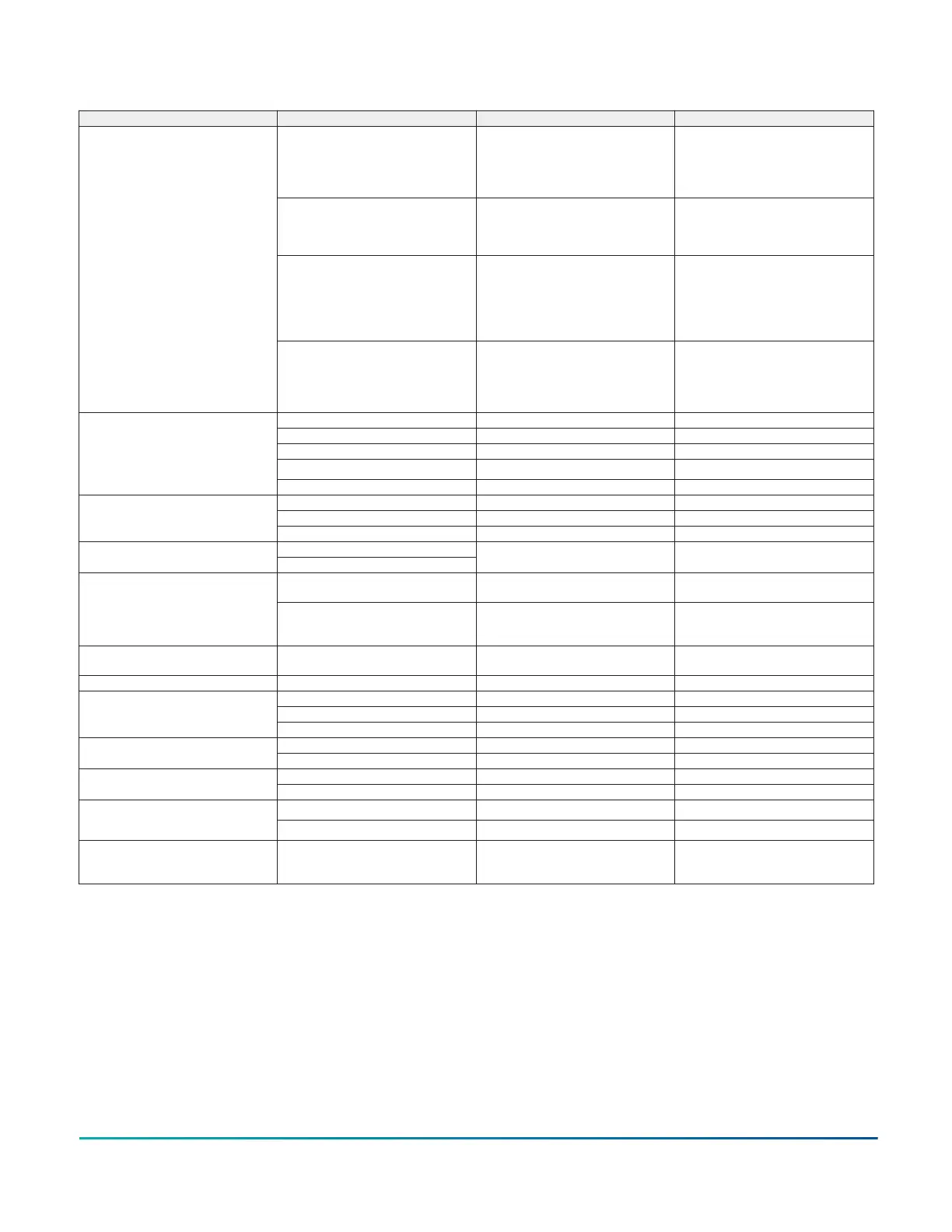
Table 56: ETC board components
Location Label Description Function and comments
LPS1 Low Pressure Switch 1
If a unit is calling for compressor operation
and after the stabilization period expires,
LPS1 detects an open contact, the
compressor will stop and the anti-short
cycle delay will start.
HPS1 High Pressure Switch 1
If a unit is calling for compressor operation
and HPS1 detects an open contact, the unit
compressor will stop and the anti-short
cycle delay will start.
LPS2 Low Pressure Switch 2
If a unit is calling for compressor operation
and after the stabilization period expires,
LPS2 detects an open contact, the
compressor will stop and the anti-short
cycle delay will start.(For units with 2-stages
of refrigeration)
D
HPS2 High Pressure Switch 2
If a unit is calling for compressor operation
and HPS2 detects an open contact, the unit
compressor will stop and the anti-short
cycle delay will start.(For units with 2-stages
of refrigeration)
C1 1 Contactor Output to Compressor
C2 2 Contactor Output to Compressor (2 stage units only)
FAN 1 Fan Contactor Output to Indoor Fan
FAN 2 No Connection
E
CN-FAN Condenser Fan Contactor Output to Condenser Fan Contactor
MV Gas Valve Input (Gas units only)
H2 H2 Output Stage 2 Gas/Electric Heat ContactorForF
H1 H1 Output Stage 1 Gas/Electric Heat Contactor
VFD
G
C
VFD Output For use with Intellispeed OptionH1
FS1 Evaporator Freeze Stat
For low evaporator temperature – Set for
26°F
H
FS2 Evaporator Freeze Stat
For low evaporator temperature – Set
for 26°F (only used for dual compressor
operation)
I PB1 Push Button Reset
Clears alarms and the stored alarms in
memory
J LED LED Operation See the Fault Code table
T1 Heat-Off-Delay 60 Seconds (Default)
T2 Heat-Off-Delay 90 SecondsK
T3 Heat-Off-Delay 120 Seconds
2COMP Compressor Selection 2-Stage Compressor (default)
L
1COMP Compressor Selection 1-Stage Compressor
ELEC Electric Heat PowerSelection for Electric Heat (default)
M
GAS Gas Heat PowerSelection for Electric Heat (default)
C 24VAC Power
N
24V 24VAC Power
O LIMIT Limit switch
Shall be interlocked to the fan relay. (When
power is interrupted from this input, the fan
will be forced on by software)
Everyday Thermostat Control operation
Compressors are controlled by the Y1 through Y2
thermostat inputs.
Single Stage Cooling Configuration
• When Y1 is energized the CN-FAN, FAN1,
and C1 outputs will energize, and the indoor
fan VFD will run at 67% speed. When Y2 is
energized, FAN2 output 2 will energize and
the VFD will run at 100% (but only if C1 is
“on”).
INSTALLATION MANUAL ZY SERIES 3-10ton 60 Hertz R-410A 101
Johnson Controls Ducted Systems