rating of 1050 Btu/ft.
3
. The result of 199,000 Btuh is
within 2% of the 200,000 Btuh rating of the furnace.
Manifold Gas Pressure
Adjustment
Single Stage
About this task:
This gas furnace has one stage of gas heat.
Therefore, the gas valve has one adjustment screw
located under a cover screw on the valve (see Figure
34).
Manifold pressure adjustment procedure.
1. Turn off all power to the unit.
2. Using the outlet pressure port on the gas
valve, connect a manometer to monitor the
manifold pressure.
3. Remove cover screw covering the pressure
adjustment screw.
4. Turn on power to the unit.
5. Set thermostat to call for heat and start
furnace.
6. If necessary, using a screwdriver, turn the
adjustment screw clockwise to increase
manifold pressure or counterclockwise to
decrease manifold pressure.
7. Once pressure has been checked, replace the
plastic cap covering the pressure adjustment
screw.
Two Stage
About this task:
This gas furnace has two heat stages. Therefore, the
gas valve has two adjustment screws located under
two cover screws. The second stage adjustment
screw is adjacent to the "HI" marking on the valve
and the first stage adjustment screw is located
adjacent to the "LO" marking on the valve (See
Figure 35 and Figure 36).
Manifold pressure adjustment procedure.
Adjust second stage pressure first (refer to Table
76 for input value), then adjust first stage pressure
(refer to Table 77 for input value).
1. Turn off all power to the unit.
2. Using the outlet pressure port on the gas
valve, connect a manometer to monitor the
manifold pressure.
3. Remove cover screws covering HI and LO
pressure adjustment screws.
4. Turn on power to the unit.
5. Set thermostat to call for second stage heat
and start furnace.
6. If necessary, using a screwdriver, turn
thesecond stage adjustment screw
(adjacent to the “HI” marking on the valve)
clockwise to increase manifold pressure
or counterclockwise to decrease manifold
pressure.
7. After the high manifold pressure has been
checked, adjust the thermostat to call for first
stage heat.
8. If necessary, using a screwdriver, turn the first
stage adjustment screw (adjacent to the “LO”
marking on the valve) clockwise to increase
manifold pressure or counterclockwise to
decrease manifold pressure.
9. Once pressure has been checked, replace the
cover screws covering the HI and LO pressure
adjustment screws.
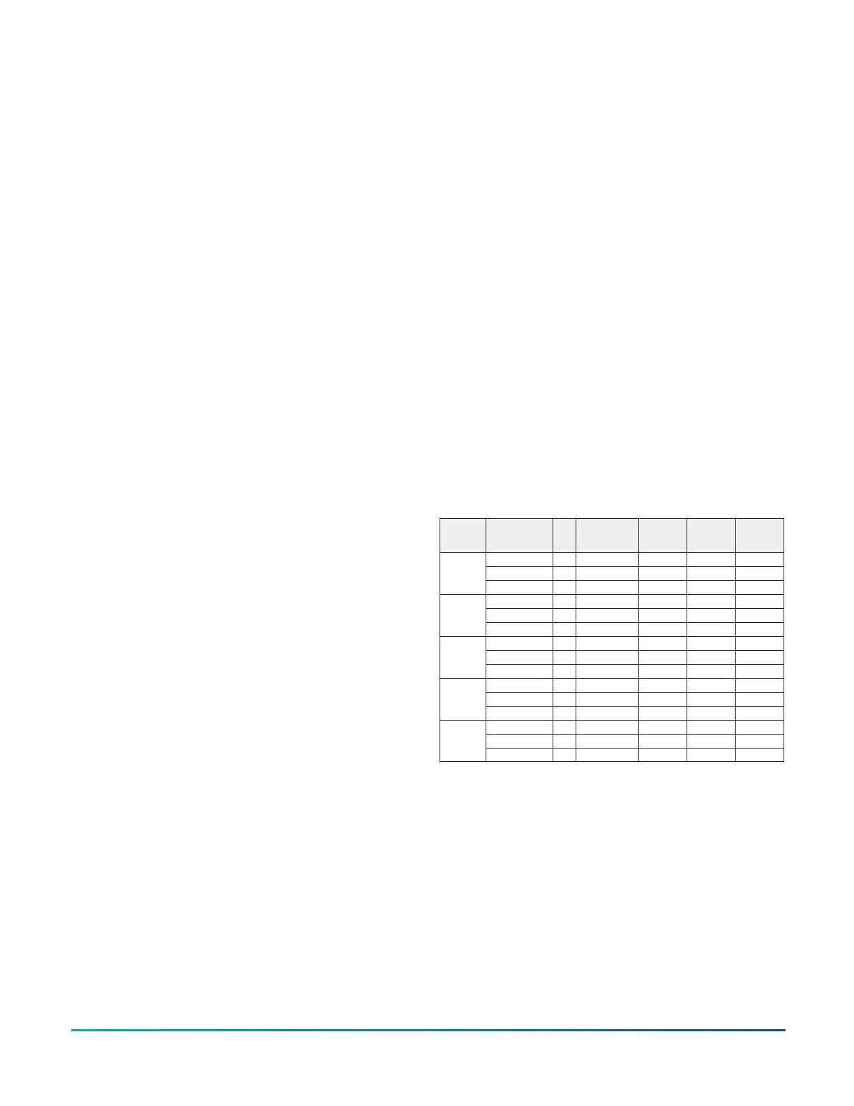
Table 77: Gas Heat Stages
Model
(Size)
Gas Heat
Description
Opt.
# of Burner
Tubes
1st Stage
Input
(Mbh)
2nd Stage
Input
(Mbh)
Total
Input
(Mbh)
Low D 2 - 70 70
Med E 3 - 114 114
ZXA7
(6)
High F 3 100 145 145
Low D 3 90 125 125
Med E 4 125 180 180
ZX08
(7.5)
High F 5 176 220 220
Low D 3 90 125 125
Med E 4 125 180 180
ZX09
(8.5)
High F 5 176 220 220
Low D 4 125 180 180
Med E 5 176 220 220
ZX12
(10)
High F 5 200 250 250
Low D 4 125 180 180
Med E 5 176 220 220
ZX14
(12.5)
High F 5 200 250 250
INSTALLATION MANUAL ZY SERIES 3-10ton 60 Hertz R-410A124
Johnson Controls Ducted Systems