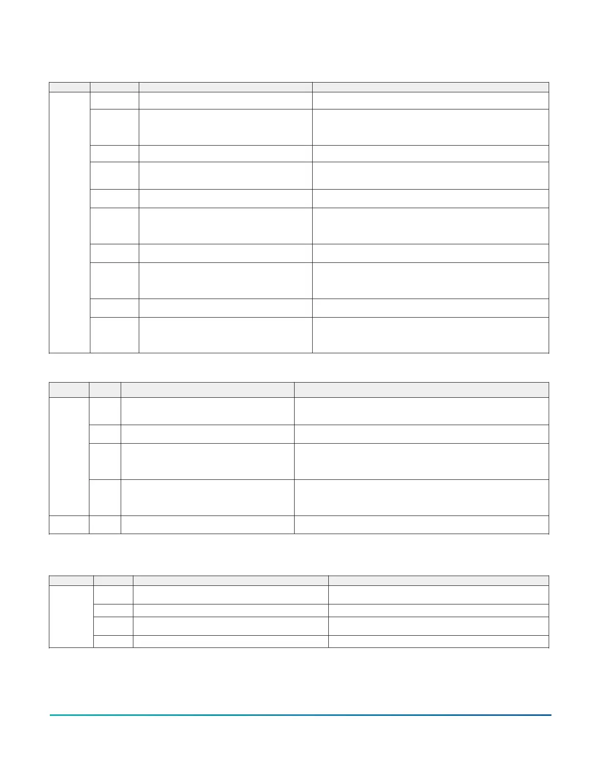
Table 68: Smart Equipment
™
UCB - refrigerant circuit safety switch and indoor blower overload
connections
Location Label Description Function and comments
HPS1
(right pin)
24 VAC hot out for refrigerant circuit 1 High Pressure Switch Connects through circuit trace to the R terminal
HPS1
(left pin)
24 VAC hot return from refrigerant circuit 1 High Pressure
Switch
Input is only considered if C1 output is needed; input must be present to allow
C1 output. Three HPS1 trips in a two hour period cause a “High Pressure Switch 1
Lockout” and C1 output is then prevented until alarm reset. Connects through circuit
trace to the right LPS1 pin.
LPS1
(right pin)
24 VAC hot out for refrigerant circuit 1 Low Pressure Switch Connects through circuit trace to the left HSP1 pin
LPS1
(left pin)
24 VAC hot return from refrigerant circuit 1 Low Pressure
Switch
Input is only considered after 30 seconds of C1 output; afterwards, input must be
present to allow C1 output. Three LPS1 trips in a one hour period cause a “Low
Pressure Switch 1 Lockout” and C1 output is then prevented until alarm reset.
HPS2
(right pin)
24 VAC hot out for refrigerant circuit 2 High Pressure Switch
Not effective for one stage compressor UCBs. Connects through circuit trace to the R
terminal
HPS2
(left pin)
24 VAC hot return from refrigerant circuit 2 High Pressure
Switch
Not effective for one stage compressor UCBs. Input is only considered if C2 output
is needed; input must be present to allow C1 output. Three HPS2 trips in a two hour
period cause a “High Pressure Switch 1 Lockout” and C2 output is then prevented
until alarm reset. Connects through circuit trace to the right LPS2 pin.
LPS2
(right pin)
24 VAC hot out for refrigerant circuit 2 Low Pressure Switch
Not effective for one stage compressor UCBs. Connects through circuit trace to the
left HSP2 pin
LPS2
(left pin)
24 VAC hot return from refrigerant circuit 2 Low Pressure
Switch
Not effective for one stage compressor UCBs. Input is only considered after 30
seconds of C2 output; afterwards, input must be present to allow C2 output. Three
LPS2 trips in a one hour period cause a “Low Pressure Switch 2 Lockout” and C2
output is then prevented until alarm reset.
FAN OVR
(right pin)
24 VAC hot out for indoor blower FAN Overload relay contact/
motor protector switch
Connects through circuit trace to the R terminal
J
FAN OVR
(left pin)
24 VAC hot return from indoor blower FAN Overload relay
contact/motor protector switch
Input is only considered if FAN output is needed; input must be present to allow
FAN output and unit operation. One FAN OVR trip lasting longer than 5 minutes or
three FAN OVR trips in a two hour period cause a “Fan Overload Lockout” and unit
operation is then prevented until alarm reset.
Table 69: Smart Equipment
™
UCB - SA BUS connections
Location Label Description
1
Function and comments
PWR Power for SA (“Sensor-Actuator”) BUS devices
Also incorporated in the J8 6-pin phone jack connector at the left-center of the board.
Positive of the 15 VDC (reading to C) circuit for powering an optional netstat and/or Multi
Touch gateway
C Common for SA BUS power and communication circuits
Also incorporated in the J8 6-pin phone jack connector at the left-center of the board.
Negative of the SA BUS circuits
– Communication for SA BUS devices
Also incorporated in the J8 6-pin phone jack connector at the left-center of the board.
Positive of the VDC (typically, a fluctuating 1.5 to 3.5 V reading to C; at least 0.25 V lower
than +) SA BUS communication circuit to optional economizer board, 4-stage board, fault
detection and diagnostics board, netstat and/or Multi Touch gateway
K
+ Communication for SA BUS devices
Also incorporated in the J8 6-pin phone jack connector at the left-center of the board.
Positive of the VDC (typically, a fluctuating 1.5 to 3.5 V reading to C; at least 0.25 V higher
than –) SA BUS communication circuit to optional economizer board, 4-stage board, fault
detection and diagnostics board, netstat and/or Multi Touch gateway
L J8 6-pin phone jack connector
Incorporates the SA BUS terminals for convenience/alternate connection of SA BUS devices,
primarily used for temporary service connection of the Multi Touch gateway
1 When wiring unit and other devices using the SA Bus and FC Bus, see Cable recommendations.
Table 70: Smart Equipment
™
UCB - user interface
Location Label Description Function and comments
Display On-board, 2-line x 8-character back-lit display
On-board display, buttons and joystick allow access to UCB, economizer, 4-
stage and FDD board parameters
ENTER Button for display menu acknowledgment and navigation
CANCEL
Button for display menu navigation and zeroing of active compressor
ASCD timer
M
JOY 4-way Joystick for display menu navigation
INSTALLATION MANUAL ZY SERIES 3-10ton 60 Hertz R-410A 107
Johnson Controls Ducted Systems
 Loading...