Chapter 3 INSTALLATION OF THE DISPLAY UNIT
3.3 INSTALLATION OF THE POWER CABLE (CFQ-5436)
3-3
3
NSTALLATION MANUAL
3.3 INSTALLATION OF THE POWER CABLE
(CFQ-5436)
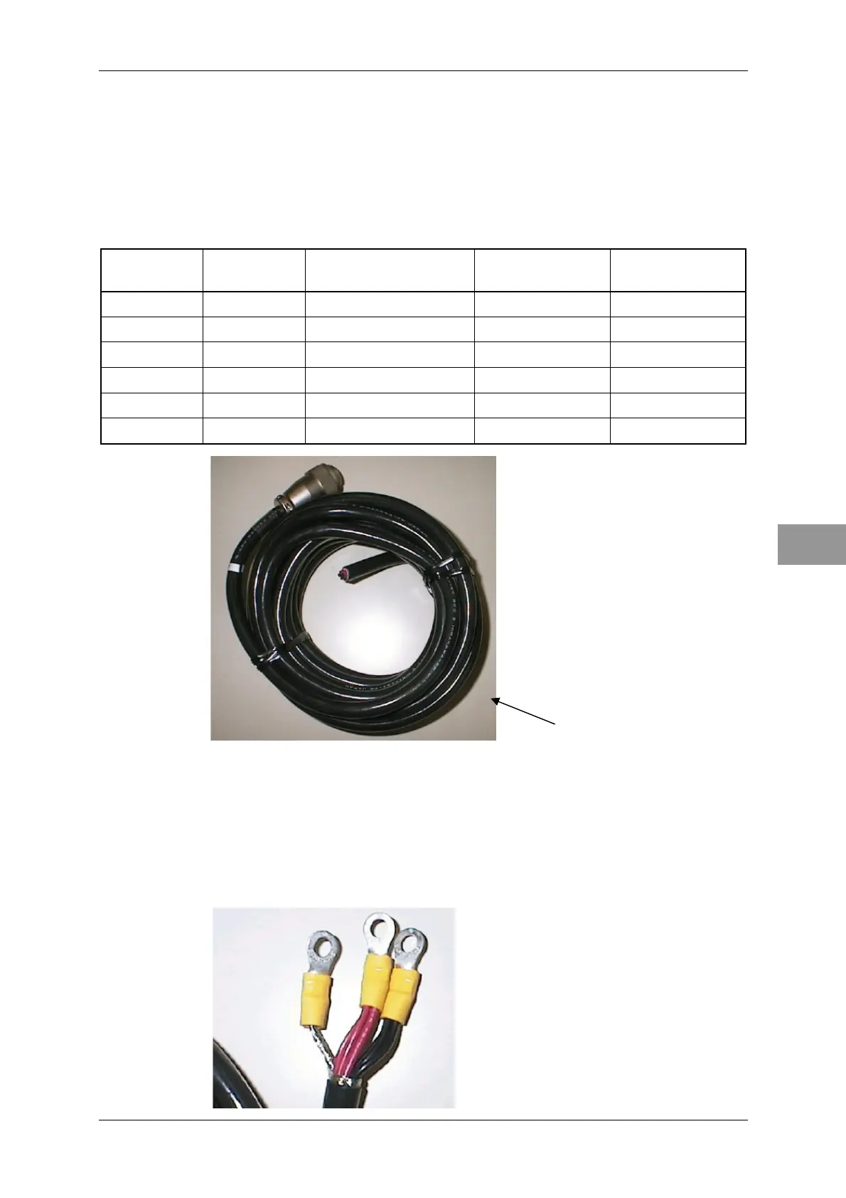
This radar equipment comes with 5-meter-long cables with a connector.
Wiring table of the cable CFQ-5436
Pin Color
Number of
wires/diameter (mm)
Cross-sectional
area (mm)
Polarity
1
Red
50/0.18
1.25 +
2
Red
50/0.18
1.25 +
3
Red
50/0.18
1.25 +
4
Black
50/0.18
1.25 -
5
Black
50/0.18
1.25 -
6
Black
50/0.18
1.25 -
Cable process method
1 Crimp three black cables together.
2 Crimp three red cables together in the same way.
3 Crimp the shielding cable.
Install the red cables on the + side of the ship's power supply, the black cables on the -
side of the ship's power supply, and the shielding cable in the hull's earth.
Cable CFQ-5436-5