4
CONNECTION
4.1.2
Control cable wiring diagram
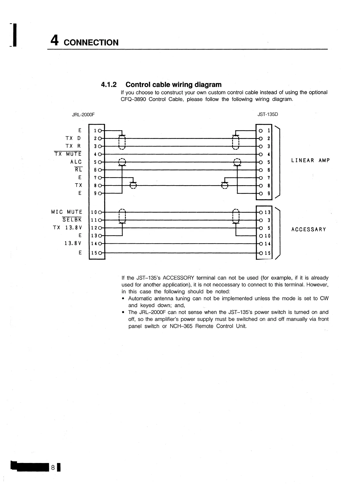
If you choose to construct your own custom control cable instead of using the optional
CFQ-3890 Control Cable, please follow the following wiring diagram.
E
TX
D
TX
R
TX MUTE
A
LC
-
RL
E
TX
E
MIC MUTE
SELBK
TX
13.8V
E
13.8V
E
If the JST-135's ACCESSORY terminal can not be used (for example, if it is already
used for another application), it is not neccessary to connect to this terminal. However,
in this case the following should be noted:
Automatic antenna tuning can not be implemented unless the mode is set to CW
and keyed down; and,
The JRL-2000F can not sense when the JST-135's power switch is turned on and
off, so the amplifier's power supply must be switched on and off manually via front
panel switch or NCH-365 Remote Control Unit.