5
OPERATING CONTROLS AND FUNCTIONS
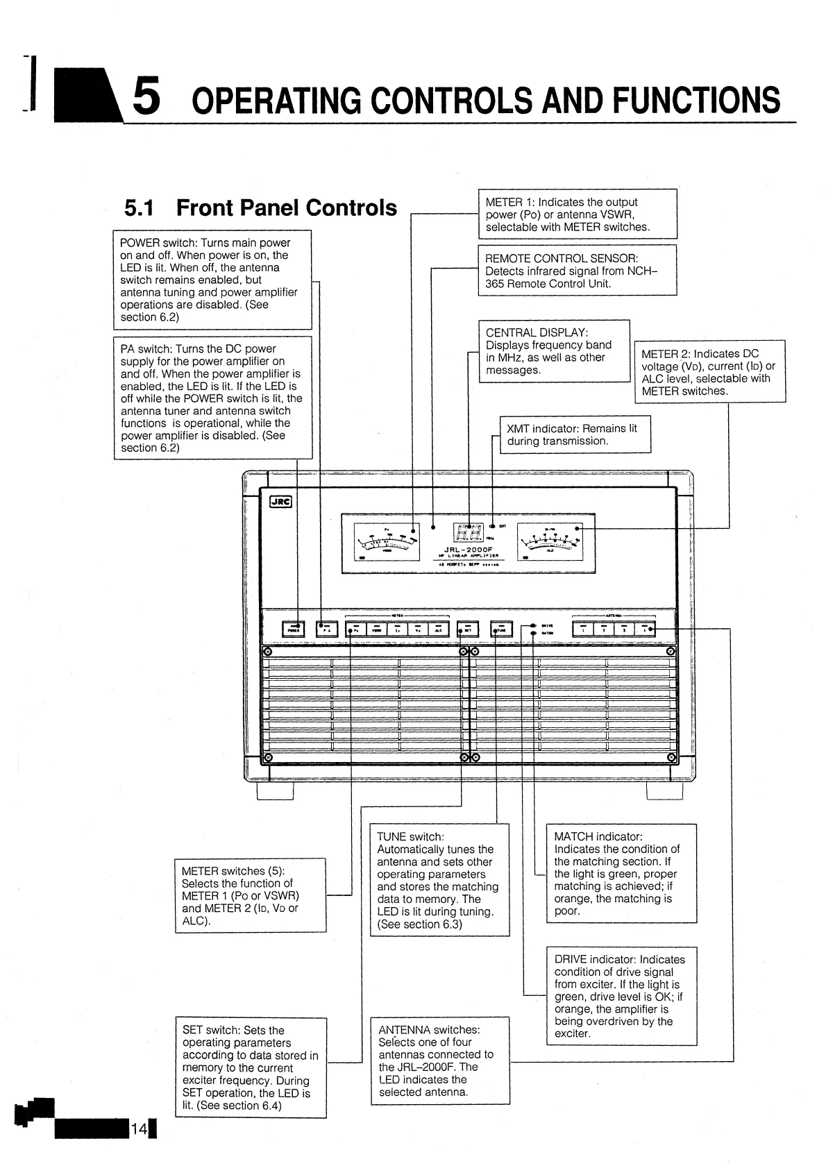
5.1
Front Panel
POWER switch: Turns main power
on and off. When power is on, the
LED is lit. When off, the antenna
switch remains enabled, but
antenna tuning and power amplifier
operations are disabled. (See
section 6.2)
Controls
METER
1:
Indicates the output
power (Po) or antenna VSWR,
Detects infrared
s~gnal from NCH-
365 Remote Control Unit.
CENTRAL DISPLAY:
Displays frequency band
in MHz, as well as other
the matching section. If
the light is green, proper
matching is achieved; if
METER
1
(Po or VSWR)
orange, the matching is
condition of drive signal
from exciter. If the light is
green, drive level is OK; if
orange, the amplifier is
operating parameters
Selects one of four
according to data stored in
antennas connected to
memory to the current
the JRL-2000F.
The
exciter frequency. During
LED indicates the