6.3.1
Automatic tuning procedures
The following instructions show how to implement the JRL-2000F's automatic tuning
operation.
@
Set the exciter as follows:
Select
CW
or
FSK
mode.
Set desired frequency.
Adjust output power of the exciter to 30
-
80
W.
@
Select the desired antenna to be matched with the antenna switch. Verify that
the selected antenna is capable of operation in the band to be tuned, and that
it is connected properly.
@
Press the button. The
LED
will light and automatic tuning begins.
If the forced transmission signal line (pin
11)
of the control terminal is connected
to the exciter, the exciter will automatically enter transmission mode. If pin
11
is
not connected, see the "Supplements" section below.
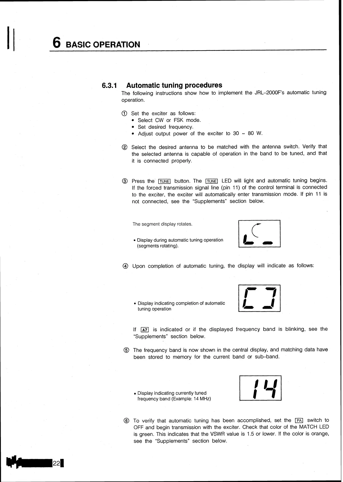
The
segment display rotates.
Display during automatic tuning operation
(segments rotating).
@
Upon completion of automatic tuning, the display will indicate as follows:
Display indicating completion of automatic
tuning operation
If
(A71
is indicated or if the displayed frequency band is blinking, see the
"Supplements" section below.
@
The frequency band is now shown in the central display, and matching data have
been stored to memory for the current band or sub-band.
Display indicating currently tuned
frequency band (Example:
14
MHz)
@
To verify that automatic tuning has been accomplished, set the
(PAI
switch to
OFF
and begin transmission with the exciter. Check that color of the
MATCH
LED
is green. This indicates that the VSWR value is
1.5
or lower.
If
the color is orange,
see the "Supplements" section below.