6.6
Adjusting
the
ALC
Level
When the JRL-2000F is operating in the Linear Amplifier Mode (as described in section
6.2),
always make sure that the ALC signal line
is
connected to the exciter's ALC terminal. The
ALC level of the JRL-2000F can be adjusted by following the steps.
@
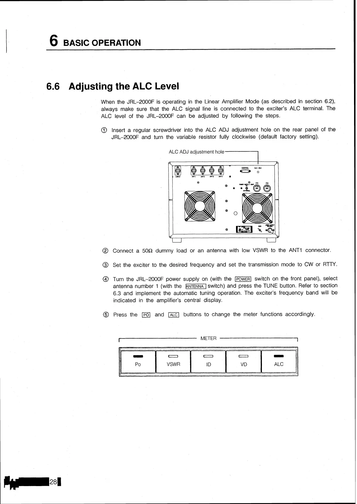
Insert a regular screwdriver into the ALC ADJ adjustment hole on the rear panel of the
JRL-2000F and turn the variable resistor fully clockwise (default factory setting).
ALC
ADJ adjustment
hole
1
IIM
MI
MI
urr
mt
o
LJ
u
@
Connect a 50R dummy load or an antenna with low VSWR to the
ANTI
connector.
@
Set the exciter to the desired frequency and set the transmission mode to
CW
or RTTY.
@
Turn the JRL-2000F power supply on (with the
-1
switch on the front panel), select
antenna number
1
(with the
-1
switch) and press the
TUNE
button. Refer to section
6.3
and implement the automatic tuning operation. The exciter's frequency band will be
indicated in the amplifier's central display.
@
Press the
a
and buttons to change the meter functions accordingly.
I
METER
1
-r.
-
Po
0
VSWR
--