SPECIAL OPERATIONS
7
7.5
Setting the
DIP
Switches
The
JRL-2000F
has DIP switches for setting the memory backup state and fro setting the
overdrive alarm settings. These DIP switches are located on the
CDJ-1143 CONTROL
printed
circuit board at the upper section of the main unit. It is visible when you remove the top
cover of the
JRL-2000F.
The functions of the DIP switches are described in the following table:
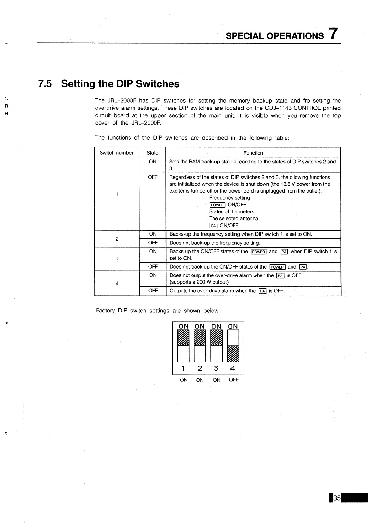
Factory DIP switch settings are shown below
Switch number
1
2
3
4
ON
ON
ON
OFF
State
ON
OFF
ON
OFF
ON
OFF
ON
OFF
Function
Sets the RAM back-up state according to the states of DIP switches
2
and
3.
Regardless of the states of DIP switches
2
and 3, the ollowing functions
are intitialized when the device is shut down (the 13.8
V
power from the
exciter is turned off or the power cord is unplugged from the outlet).
Frequency setting
lPoWER
ONIOFF
States of the meters
The selected antenna
ONIOFF
Backs-up the frequency setting when DIP switch
1 is set to ON.
Does not back-up the frequency setting.
Backs up the
ONIOFF states of the and when DIP switch
1
is
set to ON.
Does not back up the
ONIOFF states of the
-1
and
a.
Does not output the over-drive alarm when the is OFF
(supports a
200
W
output).
Outputs the over-drive alarm when the
Ipn
is OFF.