1
7
SPECIAL OPERATIONS
7.4
Using More than
4
Antennas
The JRL-2000F can be operated with up to than
4
antennas connected directly to the amplifier.
However, by utilizing common, commercially available antenna switches, the JRL-2000F can
be used with stored matching data for more than 4 antennas.
For example, by using three
antenna switches,
8
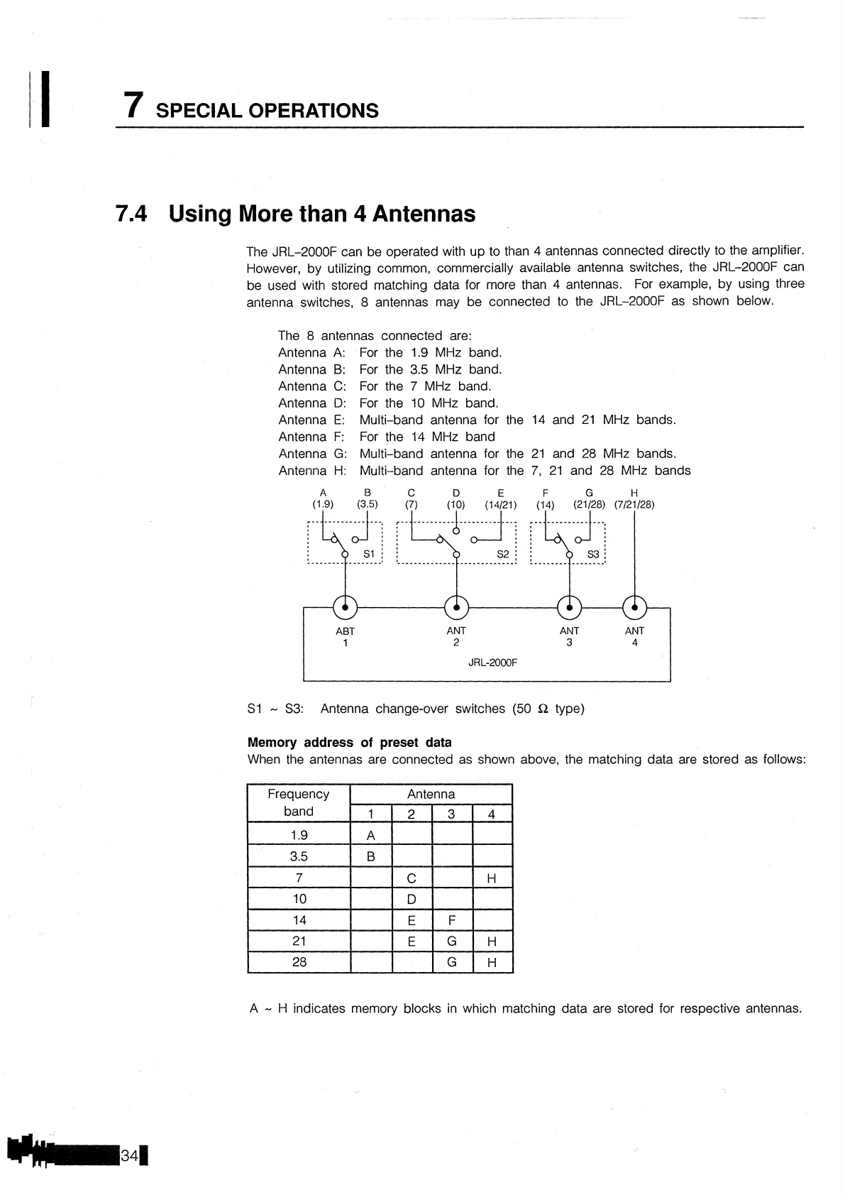
antennas may be connected to the JRL-2000F as shown below.
The
8
antennas connected are:
Antenna
A:
For the
1.9
MHz band.
Antenna
B:
For the 3.5 MHz band.
Antenna
C:
For the
7
MHz band.
Antenna
D:
For the 10 MHz band.
Antenna
E:
Multi-band antenna for the
14
and 21 MHz bands.
Antenna F: For the 14 MHz band
Antenna
G:
Multi-band antenna for the 21 and 28 MHz bands.
Antenna H: Multi-band antenna for the
7,
21 and
28
MHz bands
A
B
C
D
E
F
G
H
!..................
'......
ABT
ANT
ANT ANT
1
2
3
4
JRL-2000F
S1
-
S3: Antenna change-over switches (50
$2
type)
Memory address
of
preset data
When the antennas are connected as shown above, the matching data are stored as follows:
A
-
H indicates memory blocks in which matching data are stored for respective antennas.