SL
79
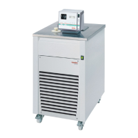
After returning the LCD display to standard display by pressing the
key , the temperature value adjusted and set on the external
voltage or current source is displayed in line 1
(Example: Eprog 50.00 °C).
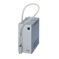
This EPROG input enables the use of different voltage and current
values as program parameters.
• “L Value” - Setting the Low value: (See below
)
1) Adjust and set the lowest desired value on the voltage or
current source (Example A: 1 V).
Wait approximately 30 seconds.
2) Assign a lower temperature threshold value to this adjusted
voltage/current value by pressing the appropriate keys on the
keypad of the instrument (Example A: 20 °C) and set by
pressing
.
• “H Value” - Setting the High value: (See below
)
1) Adjust and set the highest desired value on the voltage or
current source (Example A: 10 V).
Wait approximately 30 seconds.
2) Assign an upper temperature threshold value to this adjusted
voltage/current value by pressing the appropriate keys on the
keypad of the instrument
(Example A: 200 °C) and set by pressing .
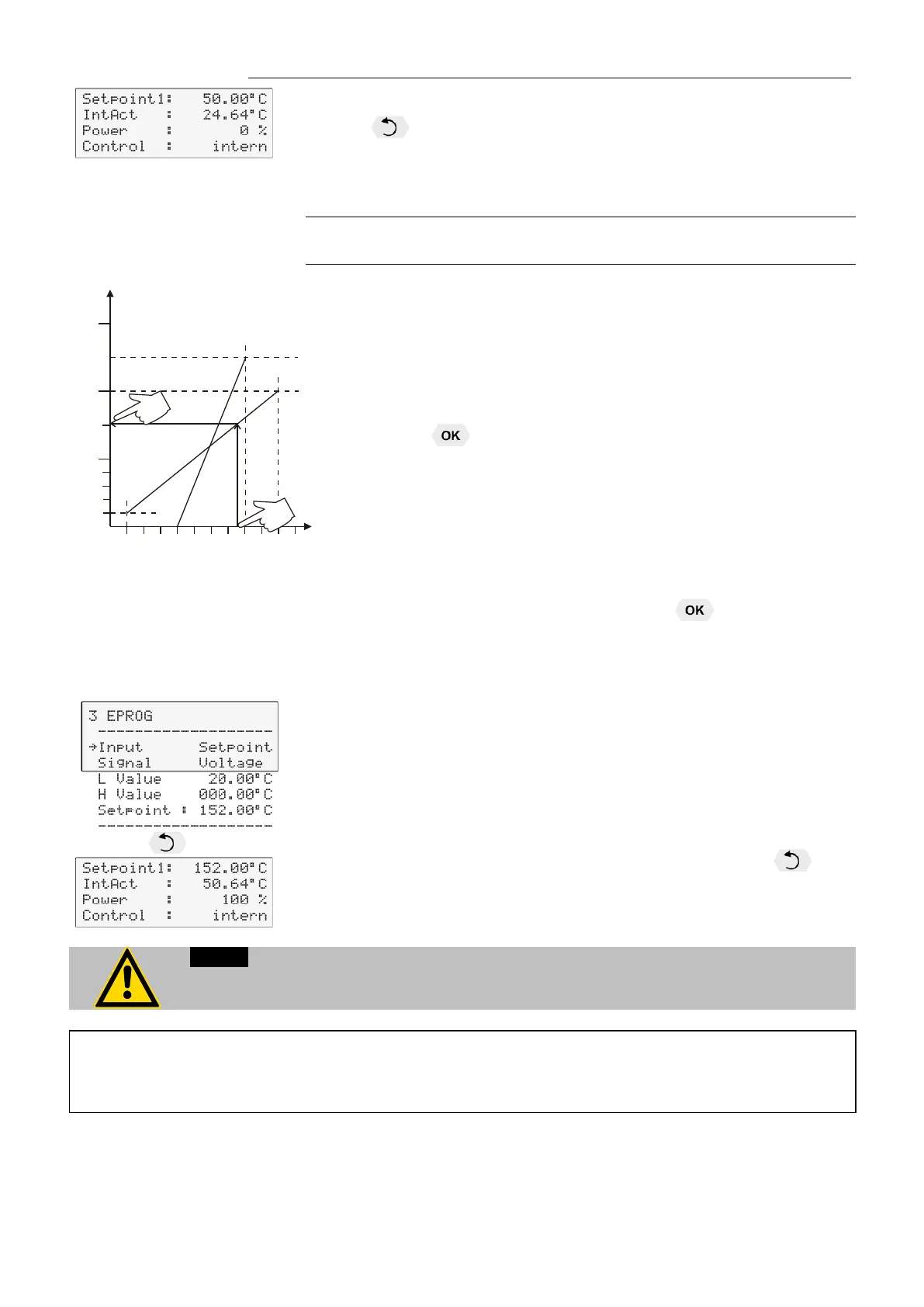
Example B in the diagram illustrates that the end point values
are freely selectable (e.g., 8 mA and 16 mA).
Example out of diagram A:
• Adjusting the voltage source for an output of 7.6 V!
Line 5 of the LCD DIALOG-DISPLAY shows the externally set setpoint
value. The instrument calculates this value from the slope of the two
specified end points (in example A, 7.6 V corresponds to an external
setpoint temperature of 152.0 °C ).
After returning the LCD display to standard display by pressing , this
value is displayed in line 1
(Example: EPROG 152.00 °C).
If this adjustment is not correctly performed at two different points, the setpoint setting
The usable temperature range between > L Value < and > H Value < is limited to the
configured working temperature range of the circulator or unit combination. For the
working temperature range, see technical specifications.
20
40
60
80
100
200
300
250
150
°C
1 2 3 4 5 6 7 8 9 10 V
2 4 6
8
10 14 18 20 mA
A
B