HST booster heater
98
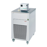
16. HST booster heater
Factory setting
Connecting cable to the REG+EPROG socket (12) of the circulator.
Heating pulse transmission of the HST booster heater.
NOTE:
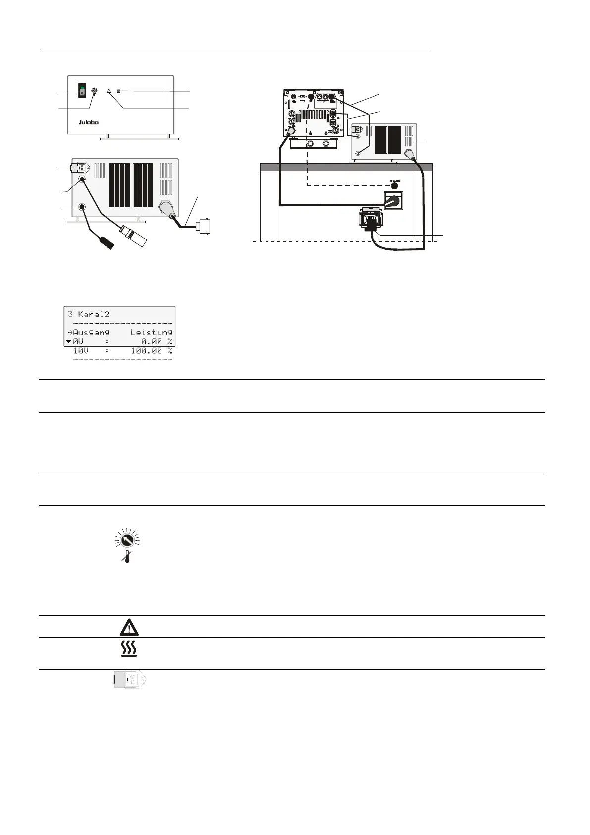
Channel 2 is pre-configured for connecting a HST booster heater (see
page 73).
If the HST booster heater is retrofitted, please check the setting for
Channel 2 because it might have been configured for a different use in
13a
Connecting cable to the control connector (13) of the circulator.
Power supply for the control electronics of the HST booster heater.
25a
Connecting cable for the HST booster heater.
Built-in mains outlet for connection of HST booster heater Not on -
FPW91-SL - 230 V/3PPE/60 Hz (see page 16)
Power supply for the heater.
30
Mains power switch, illuminated
Turn the power supply (and the HST booster heater) on and off.
31
Adjustable excess temperature protection on the HST (see page 99)
A safety device independent from the circulator. If the actual bath
temperature exceeds the adjusted safety temperature value at the
safety potentiometer, the supplementary heater is switched off
permanently.
There is an optical and audible alarm indication with a permanent
signal sound. The error is not reported to the circulator!
32
Indicator light: Alarm indication (see 31)
33
Indicator light: Heating
Blinks in time with the heating pulse/booster heater, resp.
34
Control connector 230 V / max. 1.25 A for HSP booster pump
If the ultra-low refrigerated circulator is provided with HST booster
heater and HSP booster pump, this connector replaces the unusable
control connector (14) on the rear side of the circulator. The function
is independent from the switch position of the mains power switch