3. Plug the other end of the cable into the network device.
Connect the ACX Series Router to a Management Console or Auxiliary
Device
1. Turn o the power to the console or auxiliary device.
2. Plug the RJ-45 end of the serial cable (Figure 9 on page 10 shows the connector) into the
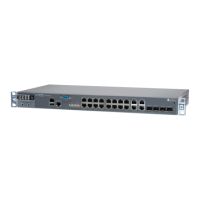
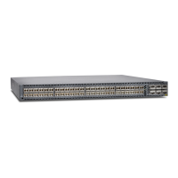
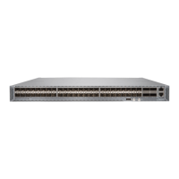
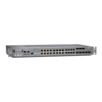
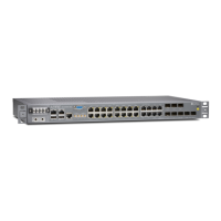
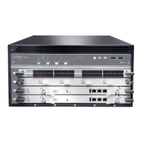
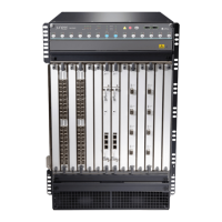
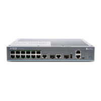
CONSOLE/AUX port on the front panel. Figure 1 on page 2, Figure 2 on page 2, and Figure 3 on
page 3 show the port.
3. Plug the female DB-9 end into the device's serial port.
Connect Network Interface Cables to the ACX Series Router
1. Have ready a length of the type of cable used by the network ports. For cable specicaons, see the
ACX1000 and ACX1100 Universal Access Routers Hardware Guide
.
NOTE: Shielded cables are required for outside deployment.
2. Remove the rubber safety plug from the cable connector port.
LASER WARNING: Do not look directly into a ber-opc transceiver or into the ends
of ber-opc cables. Fiber-opc transceivers and ber-opc cable connected to a
transceiver emit laser light that can damage your eyes.
CAUTION: Do not leave a ber-opc transceiver uncovered except when inserng or
removing cable. The safety cap keeps the port clean and prevents accidental exposure
to laser light.
3. Insert the cable connector into the cable connector port on the faceplate.
4. Arrange the cable to prevent it from dislodging or developing stress points. Secure the cable so that it
is not supporng its own weight as it hangs to the oor. Place excess cable out of the way in a neatly
coiled loop.
11
 Loading...
