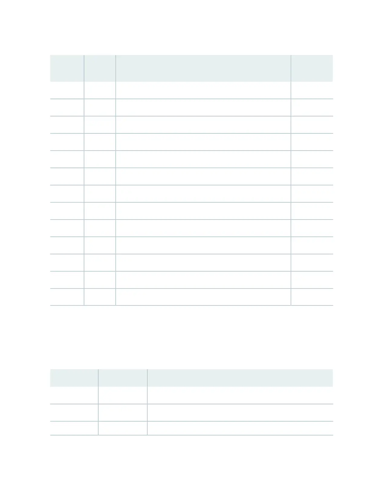
Table 3: EIA-530 DCE Connector Interface Signals for HD-26 to Female DB-25 (continued)
CircuitDescription
DB-25
Pin
HD-26
Pin
CDData terminal ready (DTR)—A (input to CTP)2012
LLLocal loopback (LL) (input to CTP)1813
BBReceive Data (RD)—B (output from CTP)1614
DDReceive Clock—B (output from CTP)915
DBTransmit Clock (from DCE)—B (output from CTP)1216
DATransmit Clock (from DTE)—B (input to CTP)1117
BATransmit Data—B (input to CTP)1418
CFData carrier detect (DCD)—B (output from CTP)1019
CCData set ready (DSR)—B (output from CTP)2220
RLRemote loopback (RL) (input to CTP)2121
TMTest mode (TM) (output from CTP)2522
GroundSignal ground (GND)724, 26
CDData terminal ready (DTR)—B (input to CTP)2325
EIA-530 Connector Interface Signal Pinouts (DB-25 Male DTE)
Table 4 on page 29 lists the EIA-530 interface signal pinouts for the HD-26 connector to the male DB-25
connector for the CTP150 platform.
Table 4: EIA-530 DTE Connector Interface Signals for HD-26 to Male DB-25
DescriptionDB-25 PinHD-26 Pin
Transmit Data—A (output from CTP)21
Transmit Clock (from DTE)—A (output from CTP)242
Transmit Clock (from DCE)—A (input to CTP)153
29
 Loading...

