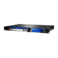
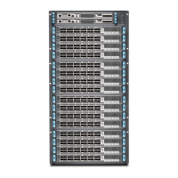
To install the device in the rack:
1. With one person standing on the left side of the device and another standing on the
right side, lift the device into the rack.
2. Position the device in its designated location in the equipment rack. Make sure the
holes of the mounting brackets align evenly with the holes of the equipment rack on
both sides.
3. Starting at the bottom of the device, have the third person secure the device in the
equipment rack by using the 10-32 x 3/8 Phillips screws.
Step 3: Install Modules and Other Components
•
Module Installation Overview on page 6
•
Protect Modules and Slots on page 6
•
Required Tools and Safety Items for Installation on page 7
•
Safety Guidelines for Installing Modules on page 7
•
Install a CTP Interface Module, Processor Module, or Clock Module on page 8
•
Install a CompactFlash Card on page 9
•
Install a PMC Module on page 10
•
Install SFPs on page 12
Module Installation Overview
In CTP2000 series platforms, interface modules can be installed in the front and rear of
the device. Rear transition modules (RTMs) are located in the rear of the device.
Interface modules are not hot-swappable.
In CTP2000 series platforms, slot numbering starts at the top of the chassis with slot 0.
Protect Modules and Slots
The CTP2056 has an ESD (electrostatic discharge) grounding jack located in the rear
lower-left corner of the chassis near the power switch. To prevent damage from
electrostatic discharge, wear an antistatic wrist strap and connect it to one of the jacks
when handling components. There are no ESD jacks on the other CTP platforms, so you
must use another grounding device.
To protect the modules, components, and slots when installing components, observe
the following guidelines:
CAUTION: When handling components, use an antistatic wrist strap
connected to an appropriate grounding device. This action helps to protect
the module from damage by electrostatic discharge.
Copyright © 2019, Juniper Networks, Inc.6
CTP2000 Series Platform Quick Start

 Loading...


