1. Wrap and fasten one end of an ESD strap around your bare wrist, and connect the other end of the
strap to the ESD point on the front of an MX10008 (see Figure 72 on page 177).
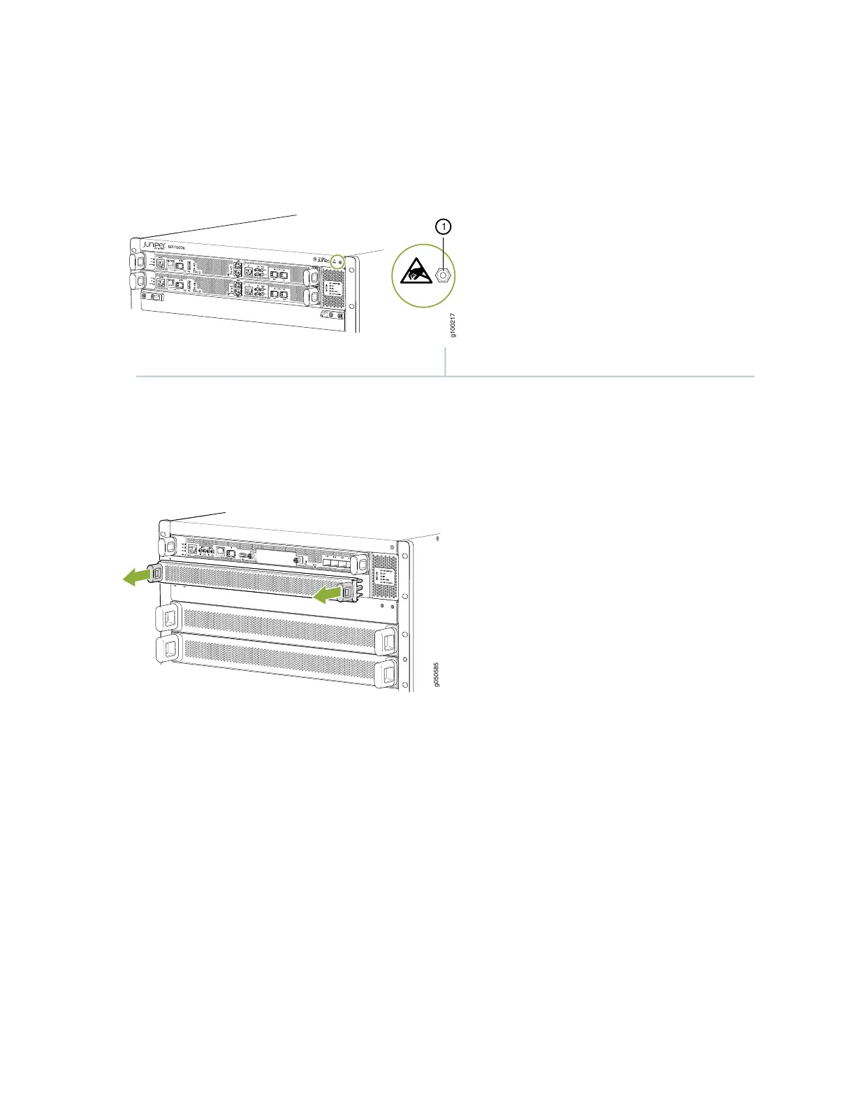
Figure 72: ESD Point for MX10008 Chassis Front
1—ESD point
2. Either remove the cover panel from the available RCB slot (see Figure 73 on page 177) or remove the
failing RCB (see “Removing a Routing and Control Board” on page 175).
Figure 73: Removing a Routing and Control Board Cover Panel
3. Remove the new RCB from the electrostatic bag and inspect it for any damage before installing it into
the chassis.
4. Lift the RCB by its sides, being careful not to strike the connectors against any object.
5. Carefully align the sides of the RCB with the guides inside the chassis.
6. Slide the RCB into the chassis, carefully ensuring that it is correctly aligned.
7. Grasp both handles and simultaneously rotate them clockwise until the RCB is fully seated and the
handles are vertical (see Figure 74 on page 178).
The RCB begins the power-on sequence after it is fully seated.
177