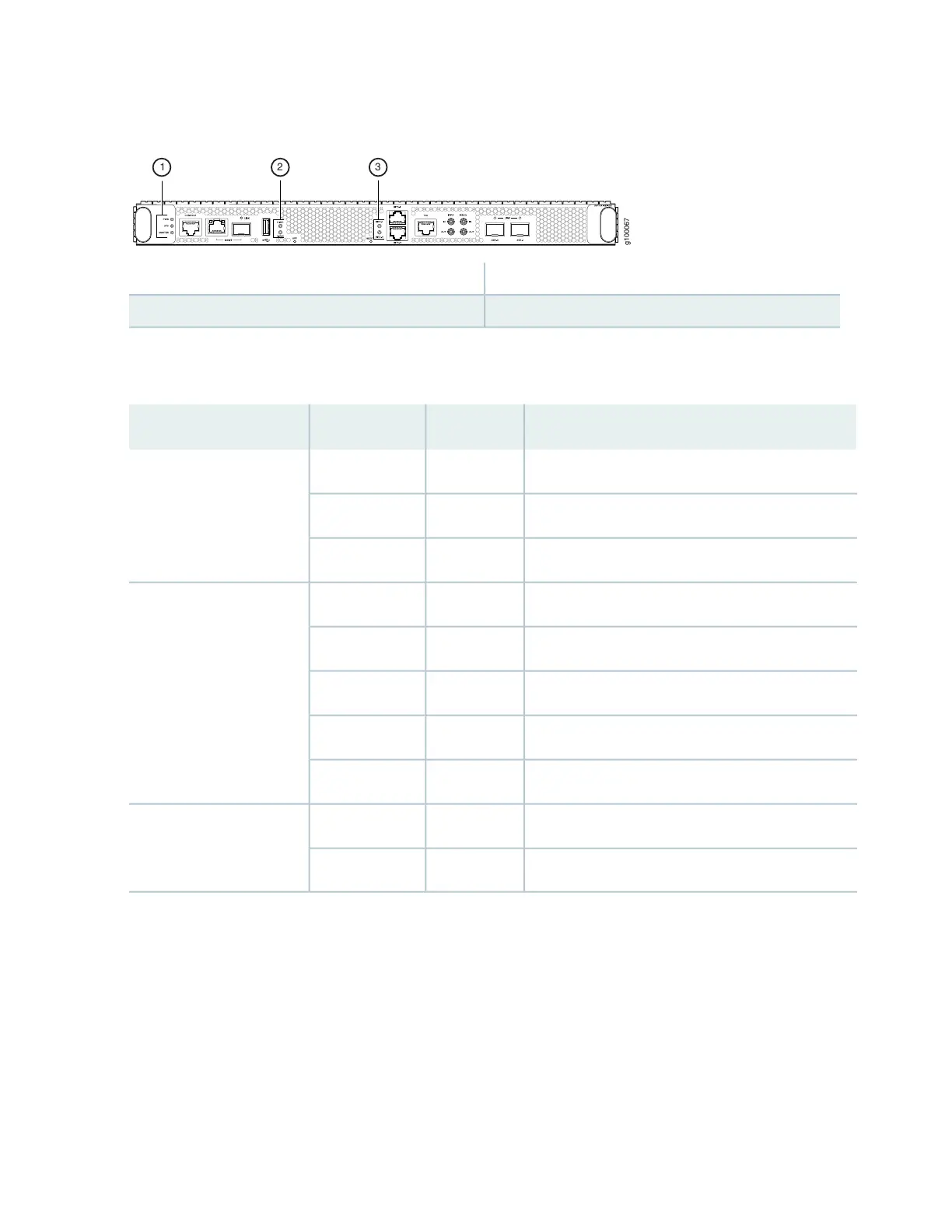
Figure 39: Routing and Control Board LEDs
3—1— Clock LEDs–BITS-0, and BITS-1Routing and Control Board status panel
2—Solid State Disk (SSD) LEDs—DISK1 and DISK2
Table 21 on page 81 describes the LEDs on the RCB status panel.
Table 21: Routing and Control Board Status LEDs
DescriptionStateColorLED
RCB is receiving adequate power.On steadilyGreenPWR
An error has been detected in the RCB.BlinkingYellow
RCB is not powered up.UnlitDark
RCB is online and functioning correctly.On steadilyGreenSTS
The beacon feature is enabled.BlinkingGreen
The RCB is booting.On steadilyYellow
An error has been detected in the RCB.BlinkingYellow
The power supply is switched off.UnlitDark
The RCB is the master.On steadilyGreenMST
The RCB is the backup.UnlitDark
Figure 40 on page 82 shows the management port LEDs on the RCB.
81