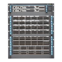
Table 35: Network Port Status LEDs (ot Interfaces)
DescriptionColor
The port is not configured.Unlit
A link is established on the ot interface.Solid green
The optical module associated with the port has a fault condition,
or the port is configured but the link is down.
Solid amber
You can also determine the configuration of the et interfaces by examining the pattern of the four Ethernet
LEDs. See Table 36 on page 105. To determine the link status and of those et interfaces, see
Table 37 on page 105.
Table 36: Valid et Interface Link Combinations of Every Two ot Ports
Configuration
et
Interface
ot Interface Data Rate
Aggregate Data
Rate
Modulation
Format 1, 3, 5Ports 0, 2, 4
2 independent 200
Gbps 16-QAM
0, 1, 2, 3200 Gbps200 Gbps4 x 100 Gigabit
Ethernet
16-QAM (x2)
Independent QPSK and
16-QAM
0, 2, 3200 Gbps100 Gbps3 x 100 Gigabit
Ethernet
QPSK and
16-QAM
Independent QPSK and
16-QAM
0, 1, 2100 Gbps200 Gbps3 x 100 Gigabit
Ethernet
16-QAM and
QPSK
2 Coupled 150 Gbps
8-QAM
0, 1, 2150 Gbps150 Gbps3 x 100 Gigabit
Ethernet
8-QAM
Independent 100G
QPSK
0,2100 Gbps100 Gbps2 x 100 Gigabit
Ethernet
QPSK and QPSK
Table 37: Ethernet Link LEDs (et Interfaces)
DescriptionColor
The et interface is down.Unlit
The et interface is up but there is no activity.Solid green
The link is up on the et interface and there is activity.Blinking green
105

 Loading...