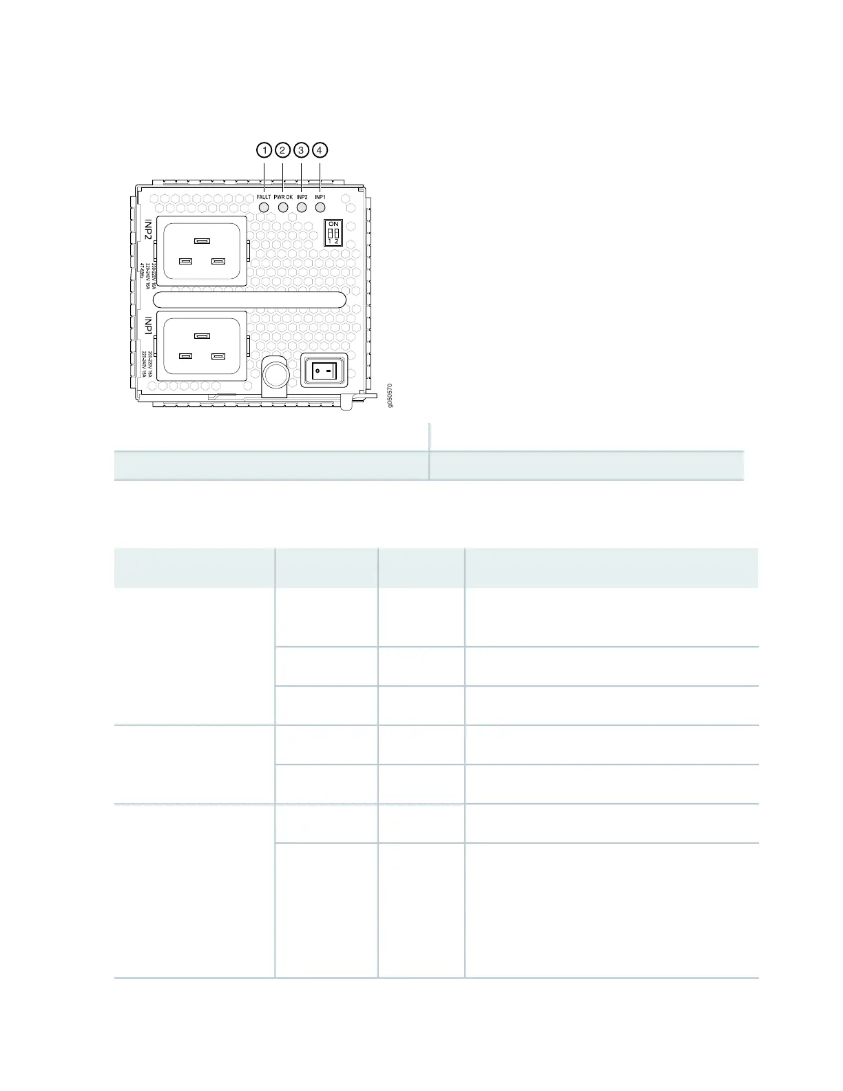
Figure 33: LEDs on an JNP10K-PWR-AC Power Supply
3—1— INP2–Source input 1FAULT
4—2— INP1–Source input 0PWR OK
Table 14 on page 71 describes the LEDs on a JNP10K-PWR-AC power supply.
Table 14: LEDs on a JNP10K-PWR-AC Power Supply
DescriptionStateColorLED
Indicates that the AC power input voltage is not
within normal operating range.
BlinkingYellowINP1 (INP0 in CLI output)
or INP2 (INP1 in CLI
output)
AC is within operating range (200–240 VAC).SolidGreen
The power supply is switched off.UnlitDark
DC power output is within normal operating range.SolidGreenPWR OK
The output is out of the limits.BlinkingYellow
Power supply is functioning normally.UnlitDarkFAULT
Power supply has failed and must be replaced. Or,
only one input is powered and the enabled router
for the input that is not powered is set to ON. See
“How to Install a JNP10K-PWR-AC Power Supply”
on page 274 for more information about the enable
switches.
SolidRed
71
 Loading...


