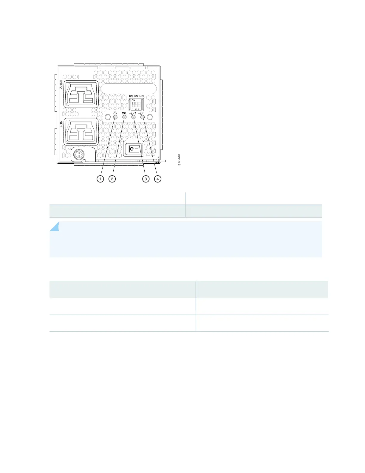
Figure 34: LEDs on a JNP10K-PWR-AC2 HVAC?HVDC Power Supply
3—1— 2 INP2–Source input 1! FAULT
4—2— 1 INP1–Source input 0OK PWR OK
NOTE: Physical markings on the power supply are INP1 and INP2. These markings correspond to
INP0 and INP1 in the show chassis power output (see Table 15 on page 73).
Table 15: Physical Markings on Chassis Versus Show Chassis Power Command
Show Chassis Power CommandPhysical Marking on JNP10K-PWR-AC2
INP0INP1
INP1INP2
Table 16 on page 74 describes the LEDs on a JNP10K-PWR-AC2 power supply.
73