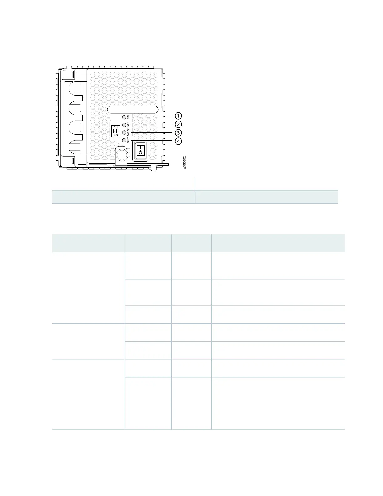
Figure 35: LEDs on a JNP10K-PWR-DC Power Supply
3—1— PWR OKINP1–Source input 0
4—2— FAULTINP2–Source input 1
Table 17 on page 75 describes the LEDs on JNP10K-PWR-DC power supplies.
Table 17: LEDs on a JNP10K-PWR-DC Power Supply
DescriptionStateColorLED
Indicates that the DC power input voltage is not
within normal operating range.
BlinkingYellowINP1 (INP0 in CLI output)
or INP2 (INP1 in CLI
output)
DC power is within operating range (-40 VDC to -72
VDC).
SolidGreen
The power supply is switched off.OffUnlit
DC power output is within normal operating range.SolidGreenPWR OK
The output is out of the limits.BlinkingYellow
Power supply has failed and must be replaced.SolidRedFAULT
Power supply is functioning normally. Or, only one
input is powered and the enable switch for the input
that is not powered is set to ON. See “Connecting
DC Power to a PTX10000” on page 235 for more
information on the enable switches.
OffUnlit
75