SSG 500 M Series Hardware Installation and Configuration Guide
56 Upgrading Memory
3. Use a phillips screwdriver to remove the screws from the top panel of the
chassis. The screws are located at the rear and sides of the panel. Keep the
screws nearby for use when closing the chassis later.
4. Grip the rear edge of the top panel, lift it up, and then remove it.
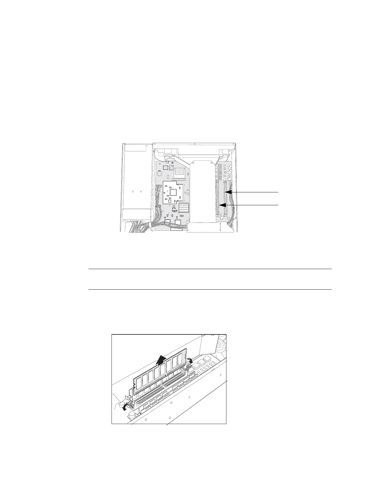
5. Locate the memory module slots (Figure 26).
Figure 26: Memory Module Slots
6. Release the 256 MB SIMM DRAM module by pressing your thumbs downward
on the locking tabs on each side of the module so that the tabs swivel away
from the module (Figure 27).
Figure 27: Removing a Memory Module
7. Grip the long edge of the memory module and slide it out. Set it aside.
Back Panel
Front Panel
Slots 1 and 2
Memory module slots
Slots 3 and 4
NOTE: Install 512 MB memory modules either in slots 1 and 3 or in slots 2 and 4. Do not
install memory modules in adjacent slots.