EN101
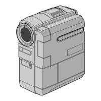
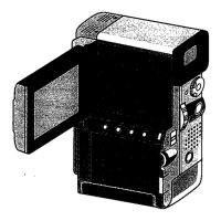
Controls
1 Snapshot Mode Button
[SNAPSHOT MODE] ..................... Z pg. 22, 30
2 Multi Screen Button
[MULTI SCREEN] ................................. Z pg. 40
3 Title/Frame [TITLE] Button .................... Z pg. 69
4 Operation Switch [ , ] .................. Z pg. 17
5 •Power Zoom Lever [T/W] .................. Z pg. 24
•Speaker/Headphone Volume
Control [VOL.] .................................. Z pg. 52
6 •Recording Start/Stop Button
[START/STOP] ................................... Z pg. 18
•Transfer Button [TRANS] .................... Z pg. 79
7 SNAPSHOT/PHOTO Button ........... Z pg. 22, 30
8 Back Light Button [BACK LIGHT] ......... Z pg. 48
9 OPEN/EJECT Switch ............................. Z pg. 12
0 Battery Release Switch
[BATT. RELEASE] .................................... Z pg. 9
! •MENU/SET Dial [+, –, PUSH] ...... Z pg. 11, 34
•LCD Monitor/Viewfinder Brightness
Control ............................................. Z pg. 21
@ Power Switch ...................................... Z pg. 17
# Play/Pause Button [
4
/6] ...................... Z pg. 52
$ Rewind Button [
2
] ............................ Z pg. 52
% Stop Button [5] ................................... Z pg. 52
^ Fast-Forward Button [
3
] .................... Z pg. 52
& Lock Button ......................................... Z pg. 17
* Diopter Adjustment Control ................. Z pg. 10
Connectors
The connectors
(
to
q
are located beneath the cover.
( Digital Video Connector
[DV OUT] (i.link*) ................... Z pg. 72, 73, 75
*i.Link refers to the IEEE1394-1995 industry
specification and extensions thereof. The logo
is used for products compliant with the i.Link
standard.
) •Audio/Video Output Connector
[AV OUT] ......................................... Z pg. 70
• Headphones Connector [ ] ............. Z pg. 90
q Multi Connector
When attached to the Docking Station, this part is
connected.
Indicators
w Tally Lamp ........................................... Z pg. 18
e Power Lamp ........................................ Z pg. 18
Other Parts
r Flash ................................................... Z pg. 32
t Flash Sensor ........................................ Z pg. 32
Be careful not to cover this area, as it contains a
sensor required by the flash.
y Camera Sensor
Be careful not to cover this area; a sensor
necessary for shooting is built-in here.
u Lens Cover
Opens when the viewfinder is pulled out or the
LCD monitor is opened fully.
i Stereo Microphone .............................. Z pg. 90
o Viewfinder ........................................... Z pg. 10
p •Remote sensor .................................. Z pg. 80
•Infrared Transmitter/Receiver ............. Z pg. 78
Q LCD Monitor ....................................... Z pg. 21
W Speaker ............................................... Z pg. 52
E Battery Pack Mount ............................... Z pg. 9
R Grip Strap ............................................ Z pg. 10
T Card Cover .......................................... Z pg. 14
Y Cassette Cover ..................................... Z pg. 12
U Stud Hole ............................................ Z pg. 70
I Tripod Mounting Socket ................. Z pg. 16, 70