70 EN
12
3
A
B
PLAYBACK
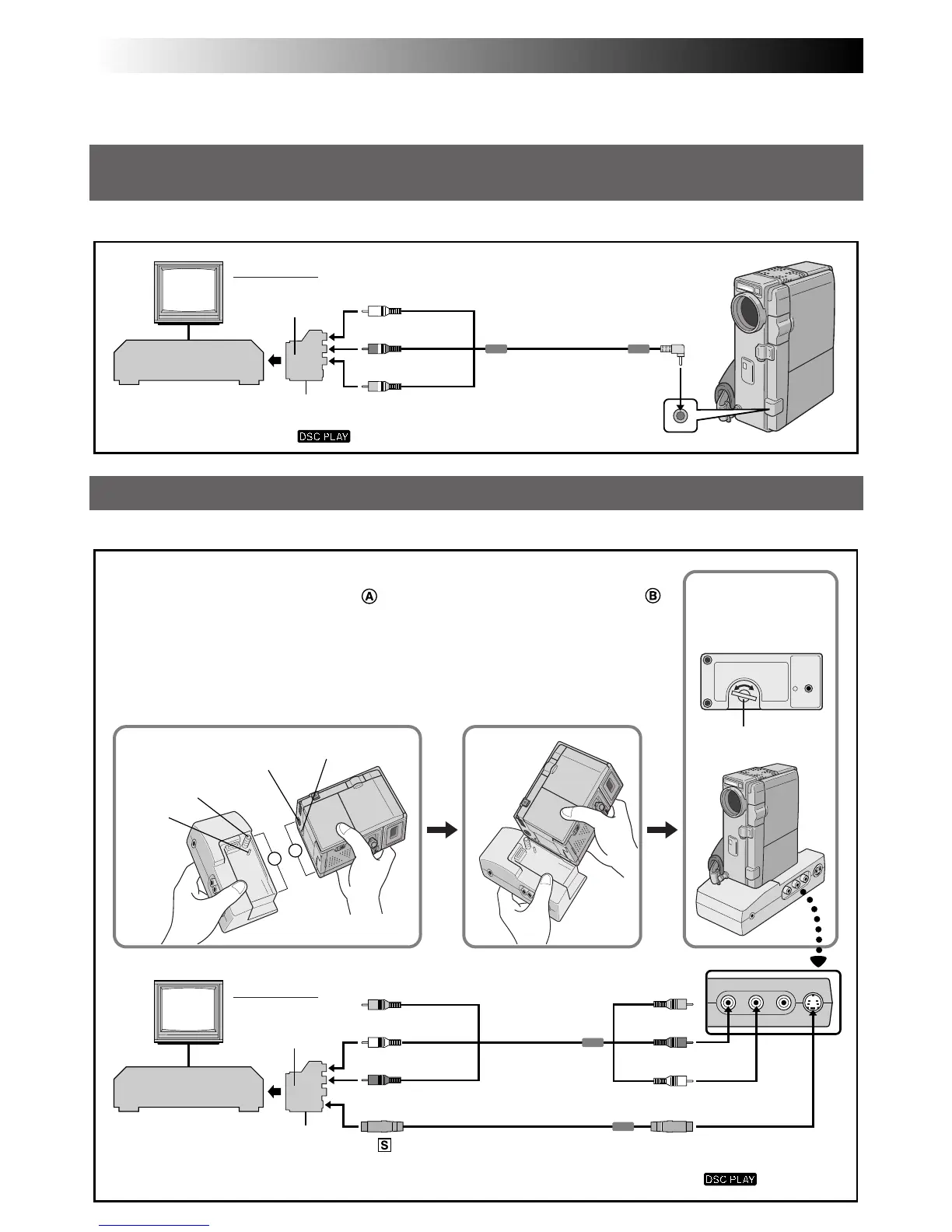
Basic Connections
These are some basic types of connections. When making the connections, refer also to your VCR and TV
instruction manuals.
A. Connection to a TV or VCR equipped with a SCART connector compatible only with regular video
signal
Use the provided Audio/Video (A/V) cable [mini-plug to RCA plug].
B. Connection to a TV or VCR equipped with a SCART connector compatible with Y/C signal
Use the provided Docking Station, Audio/Video (A/V) cable [RCA plug to RCA plug] and S-Video cable.
TV
VCR
Yellow to VIDEO
A/V cable
[mini-plug to RCA
plug] (provided)
Red to AUDIO R OUT**
White to AUDIO L OUT**
Red to AUDIO R**
White to AUDIO L**
Yellow:
Not connected
Screw Knob
Screw
Stud
Bottom of
Docking Station
Stud hole
To
-IN
To
AV OUT
Cable Adapter
(provided)
Set to CVBS
Tripod mounting socket
White to AUDIO L**
Red to AUDIO R**
Yellow:
Not connected
To S-VIDEO OUT
S-Video cable (provided)
A/V cable
[RCA plug to RCA
plug] (provided)
Cable Adapter
(provided)
Set to Y/C
TV
VCR
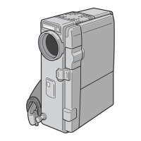
Docking Station Attachment
1 Align the edge of the camcorder with the edge of the Docking Station .
2 Align the direction stud and screw on the Docking Station with the stud hole
and tripod mounting socket on the camcorder.
3 Tighten the screw.
•When removing the camcorder, loosen the screw and detach the camcorder.
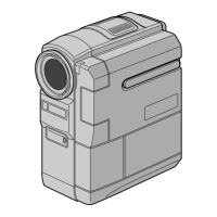
Connector
cover*
* When connecting the cables, open this cover.
To TV or VCR
To TV or VCR
** The Audio cable is not required for watching still images with
the Power Switch set to “ ”.
** The Audio cable is not required for watching still images with the Power Switch set to “ ”.