(No.MB191)1-15
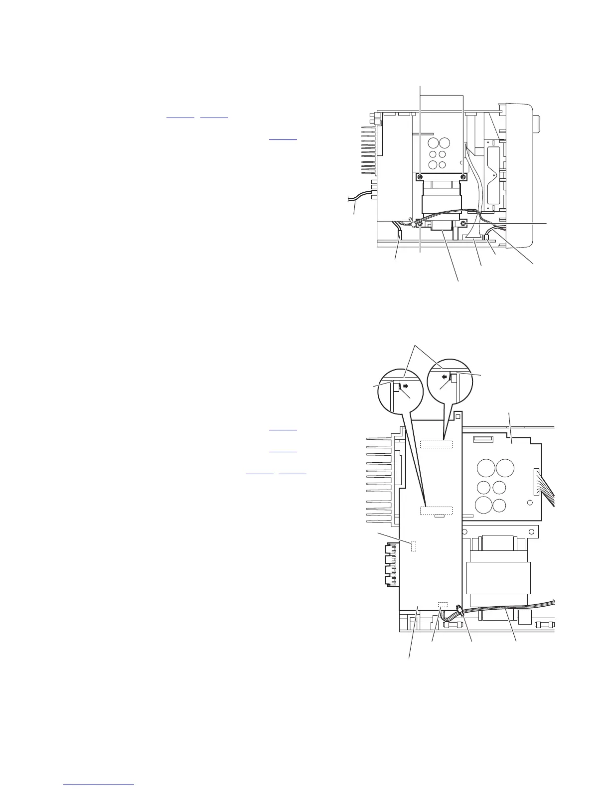
3.1.10 Removing the transformer board
(See Fig.18)
• Prior to performing the following procedure, remove the metal
cover, tuner, video board, rear panel and center chassis as-
sembly.
(1) From the top side of the main body, disconnect the wires
from the connectors (CN119
, CN250) on the transformer
board.
(2) Disconnect the parallel wire from the connector CN101
on
the transformer board.
(3) Remove the four screws Q attaching the transformer board
and take out the transformer board from the main board.
Fig.18
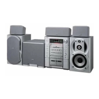
3.1.11 Removing the speaker terminal board
(See Fig.19.)
• Prior to performing the following procedure, remove the metal
cover, tuner, video board, rear panel, main board and center
chassis assembly.
(1) From the top side of the main body, remove the tie band fix-
ing the parallel wire.
Reference:
After connecting the parallel wire, fix it with the new tie
band.
(2) Disconnect the parallel wire from the connector CN106
on
the speaker terminal board.
(3) Disconnect the parallel wire from the connector CN219
on
the primary board.
(4) Release the locks (i, j) of the connectors (CN205, CN214)
and disconnect the speaker terminal board in an upward di-
rection.
Fig.19
CN250
Power
cord
Q
CN119
CN101
Wire
Transformer board
Q
Q
Speaker terminal board
Speaker terminal board
CN214
CN205
CN106
CN219
Tie band
Primary board
Parallel wire
i
j