1-10 (No.MB206)
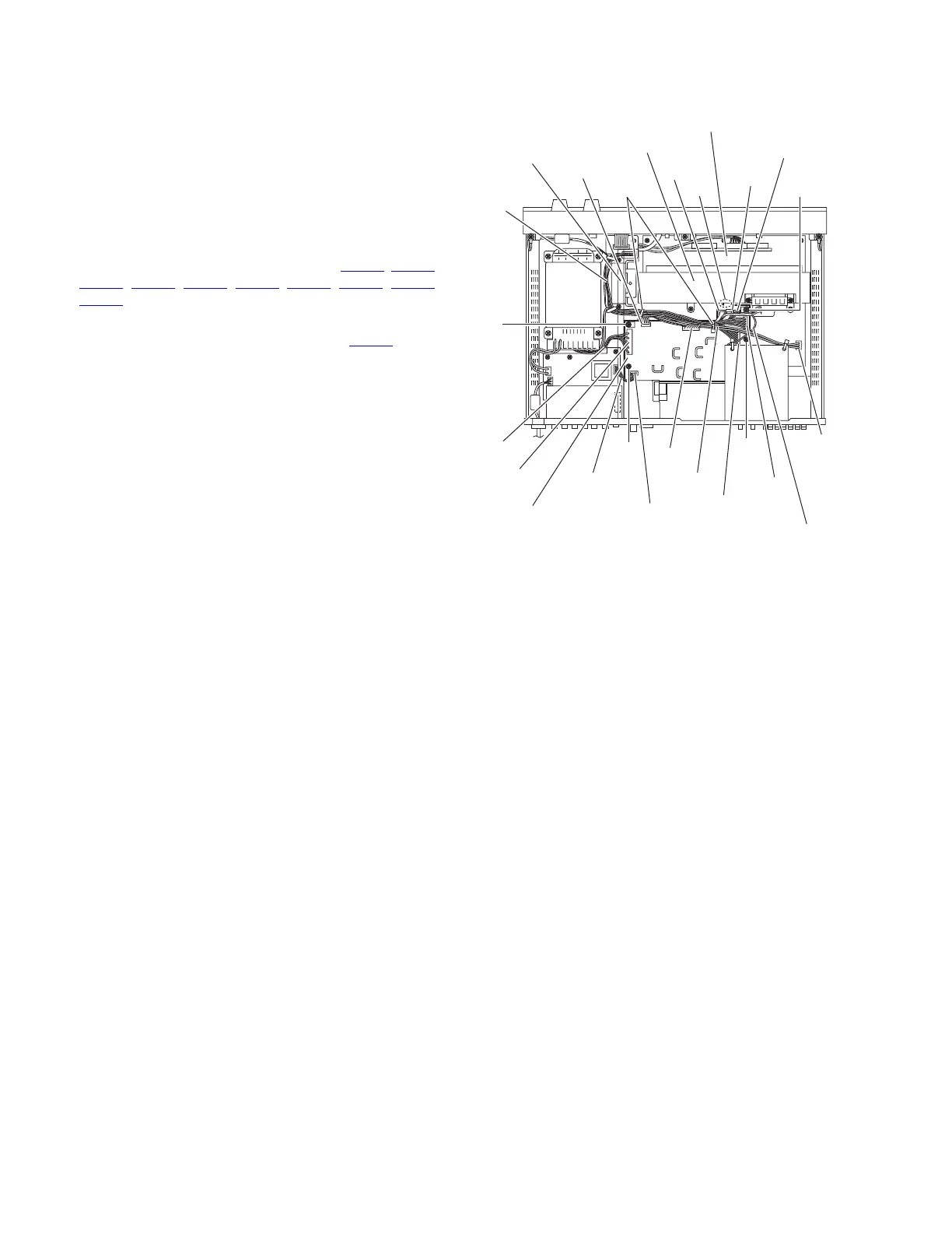
3.9 Removing the secondary board
(See Fig.12)
• Remove the top cover.
(1) From the top side of the main body, remove the divider.
Reference:
When reassembly, attach the divider as before.
(2) Remove the tie bands bundling the wires.
Reference:
After reassembling, bundle the wires with the new tie
bands as before.
(3) Disconnect the wires from the connectors (CN201
, CN207,
CN208
, CN211, CN216, CN261, CN412, CN510, CN520,
CN721
) on the secondary board.
Reference:
Disconnect the wire from the connector CN702
on the
main amplifier board as required.
(4) Remove the three screws M and screw M' attaching the
secondary board.
Reference:
When attaching the screw M', attach the earth wire with
it.
(5) Take out the secondary board from the main body.
Reference:
When attaching the secondary board, insert the section
e of the secondary board in the hole of the heat sink and
attach the secondary board.
Fig.12
Main amplifier board
Wires
Wire
Wire
CN211
CN216
CN207
CN510
CN520
CN721
Earth wire
CN702
Heat sink
e
Divider
CN412
Tie bands
Secondary board
CN201
CN261
CN208
M
M
M'
M
www.freeservicemanuals.info
Published in Heiloo, Holland.

 Loading...