(No.MB206)1-9
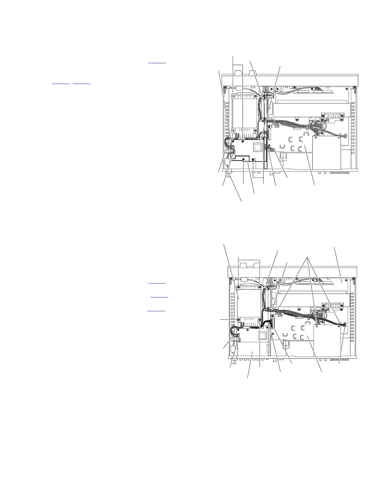
3.7 Removing the primary board
(See Fig.10)
• Remove the top cover and video/audio I/O board.
(1) From the top side of the main body, remove the divider.
(2) Disconnect the wire from the connector CN208
on the sec-
ondary board.
(3) Disconnect the wire and power cord from the connectors
(CN202
, CN203) on the primary board.
(4) Remove the four screws K and screw K' attaching the pri-
mary board.
Reference:
When attaching the screw K', attach the barrier with it.
(5) Take out the primary board from the main body.
Fig.10
3.8 Removing the power transformer
(See Fig.11)
• Remove the top cover.
(1) From the top side of the main body, remove the tie bands
and wire clamp bundling the wires.
Reference:
After reassembling, bundle the wires with the new tie
bands and wire clamp as before.
(2) Disconnect the wire from the connector CN201
on the sec-
ondary board.
(3) Disconnect the wire from the connector CN202 on the pri-
mary board.
(4) Disconnect the wire from the connector CN702
on the main
amplifier board.
(5) Remove the four screws L attaching the power transform-
er.
(6) Take out the power transformer from the main body.
Fig.11
Divider
K
K' K
Wire
Wire
CN203
CN202
CN208
Secondary board
Power cord
Barrier
Primary board
Main amplifier board
Wires
Wire clamp
Power transformer
Tie bands
Secondary board
Primary board
CN702
CN201
CN202
Wire
Wire
L
L
L
www.freeservicemanuals.info
Published in Heiloo, Holland.

 Loading...