1-10 (No.22036)
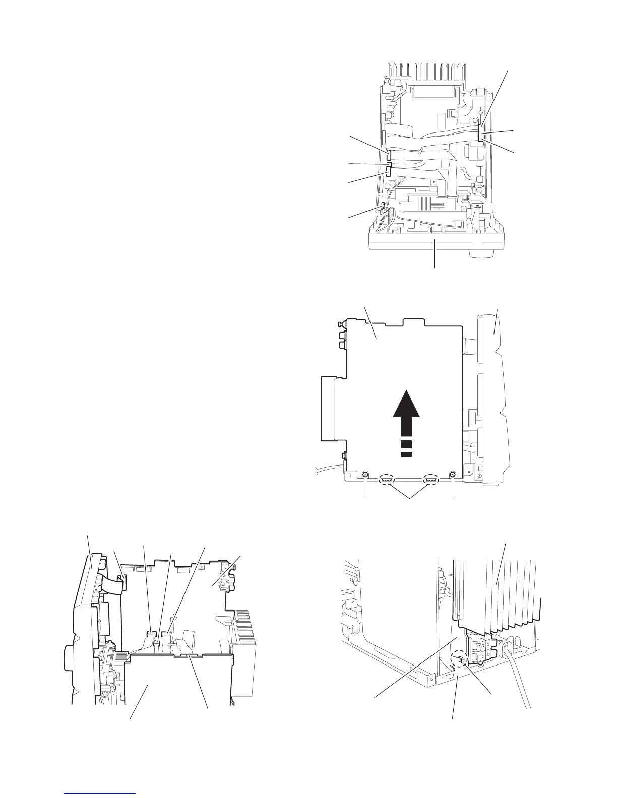
2.1.7 Removing the power amplifier board / power amplifi-
er sub board / main board / heat sink
(See Fig.13 ~ 21)
• Prior to performing the following procedure, remove the metal
cover, the rear cover, the CD-R mechanism assembly and the
rear panel.
(1) Disconnect the card wire from connector CN900, CN901,
CN933 and CN931 on the main board respectively.
(2) Disconnect the wire from connector CN949, CN950 and
CN951 on the power supply board.
(3) Remove the two screws I on the right side of the body.
(4) Move the boards and heat sink assembly upwards and dis-
engage the joint d and the two joints e to release the power
amplifier board and the main board from the chassis (Refer
toFig.15 , 16).
Move the rear part of the board and heat sink assembly to
the right side.
CAUTION:
The wire extending from the lower side of the main board
is still connected with the body (Refer to Fig.17).
(5) Disconnect the wire from connector CN906 on the lower
side of the main board (Refer to Fig.18).
2.1.8 Removing the power amplifier board
(See Fig.19 ~ 21)
(1) Disconnect the power amplifier board from connector
CN941 on the power amplifier sub board.
2.1.9 Removing the power amplifier sub board
(See Fig.19 ~ 21)
(1) Disconnect the two wires from connector CN944, CN945,
CN946 and CN947 on the power amplifier sub board.
(2) Remove the two screws J attaching the power amplifier
sub board and the heat sink.
2.1.10 Removing the main board
(See Fig.19 ~ 21)
(1) Disconnect the wires from connector CN944, CN945,
CN946 and CN947 on the power amplifier sub board.
(2) Remove the two screws K attaching the main board and
the heat sink.
REFERENCE:
The power amplifier board, the power amplifier sub board, the
main board and the heat sink can be remove drespectively.
Fig.13
Fig.14
Fig.15
Fig.16
CN931
CN901
CN900
Main board
Power supply board
CN949 / CN950 / CN951
Front panel assembly
CN933
Main board
CN900
Power supply board
CN949
Front panel assembly
CN950
CN951
CN933
CN931
CN901
Joint e
Main board
Front panel assembly
II
Joint d
Chassis
Heat sink
Power amplifier board

 Loading...