(No.22036)1-17
2.2.3 Removing the head amplifier & mechanism control
board
(See Fig.4 and 5)
(1) Remove the flexible wire from the connector CN31 on the
head amplifier & mechanism control board on the rear of
the cassette mechanism assembly.
(2) Remove the three screws B retaining the head amplifier &
mechanism control board.
(3) Disconnect the connector CN 32 on the head amplifier &
mechanism control board from the connector CN1 on the
reel pulse board, and remove the head amplifier & mecha-
nism control board.
Note:
When necessary, remove the 4 pin parallel wire soldered to
the main motor.
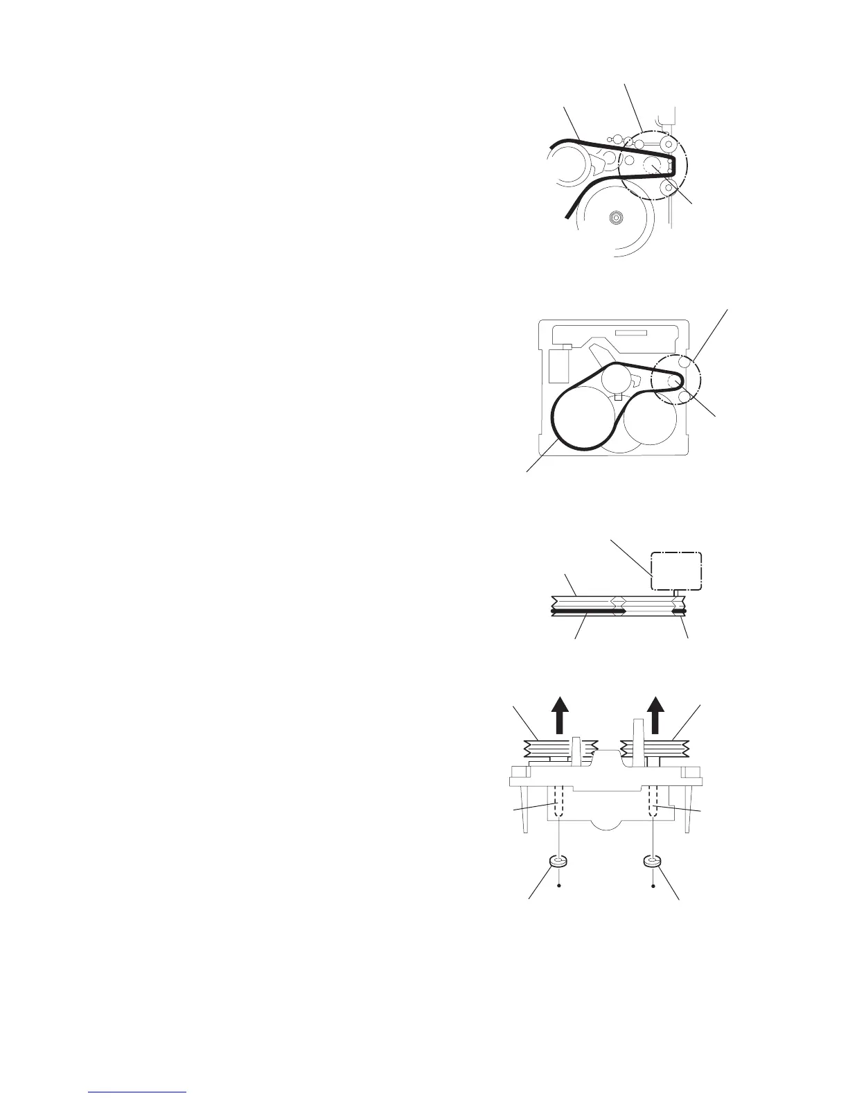
2.2.4 Removing the main motor
(See Fig.4 to 7)
• Prior to the following procedure, it is not necessary to remove
the head amplifier & mechanism control board.
(1) Remove the two screws C retaining the main motor.
(2) While raising the main motor, remove the capstan belt from
the motor pulley.
CAUTION:
Be sure to handle the capstan belt so carefully that this belt will
not be stained by grease and so on. Moreover, this belt should
be hanged while referring to the capstan belt hanging method
in Fig. 6 and 7.
Fig.4
Fig.5
Fig.6
Fig.7
main motor assembly
capstan belt
motor pully
main motor assembly
capstan belt
motor pully
main motor assembly
capstan belt
fly wheel
motor pully
capstan shaft (L)
fly wheel (L)
capstan
shaft (R)
fly wheel (R)
slit washer d slit washer c

 Loading...