1-14 (No.22036)
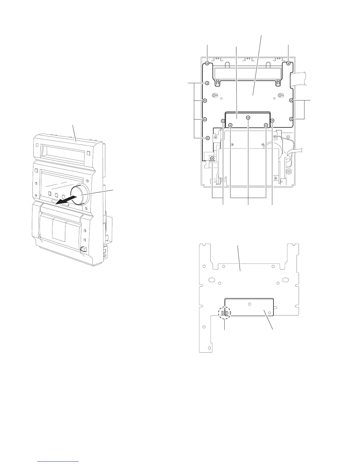
2.1.13 Removing the display board / switch board
(See Fig.26 ~ 28)
• Prior to performing the following procedure, remove the front
panel assembly.
(1) Pull out the VOLUME knob on the front panel.
(2) Remove the eleven screws N on the back of the front panel
and remove the display board with the switch board.
(3) Remove the three screws O attaching the switch board to
the LCD holder.
(4) If necessary, unsolder the wire connected to connector
FW931 on the display board and FW931 on the switch
board.
Fig.26
Fig.27
Fig.28
Front panel assembly
VOLUME knob
N
N
N
N
NN
Switch board
Display board
O
Switch board
Display board
FW931

 Loading...