XV-N5SL
8
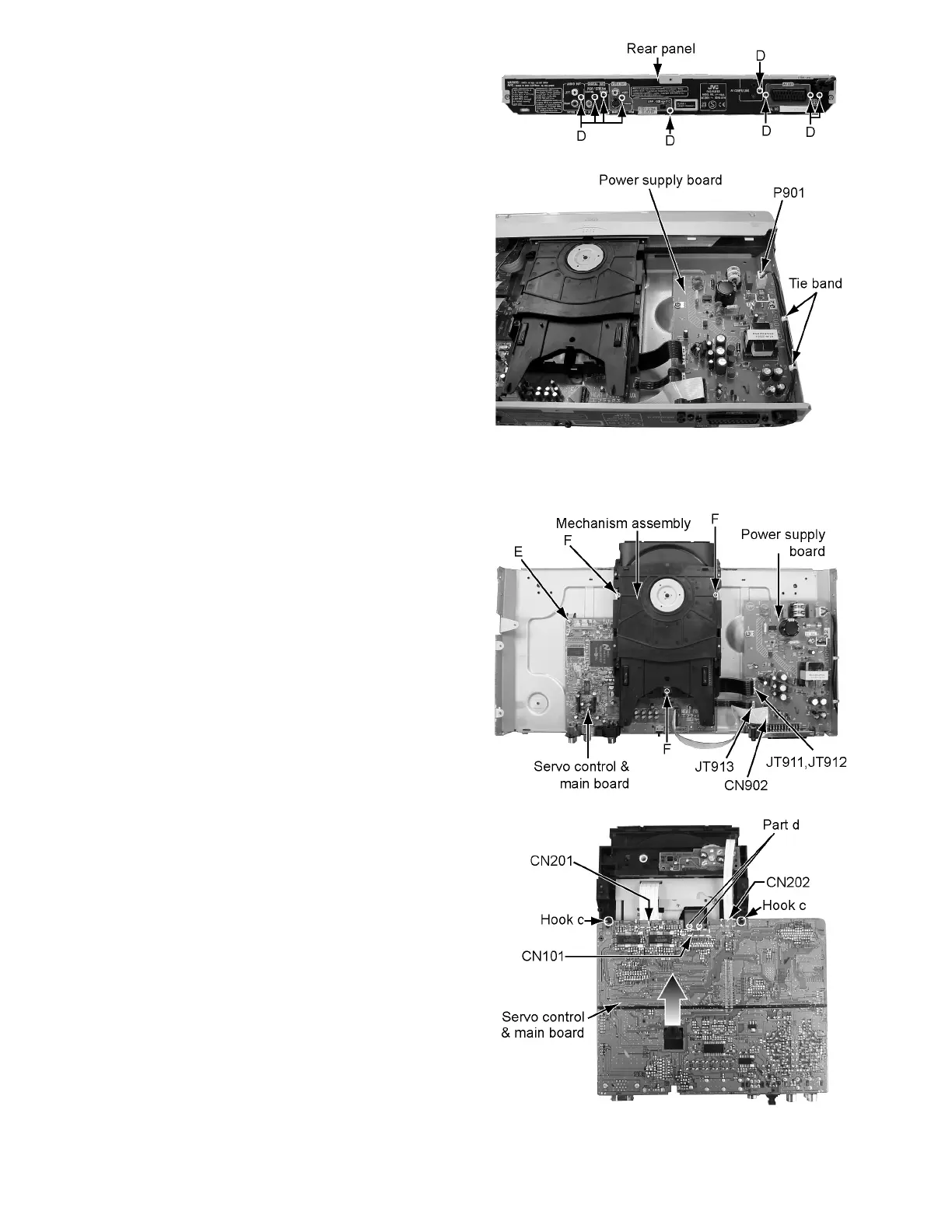
2.1.3 How to remove a rear panel
(See Figure 5 and 6)
• Please remove a top cover before removing a rear panel.
(1) Screw D attaches a rear panel to the main part. Remove
the nine screws D.
(2) Extract a power cord from socket P901 on a power supply
board.
(3) Remove two tie bands.
Fig.5
Fig.6
2.1.4 How to remove a mechanism assembly
& servo control board
(See Figure 7 and 8)
• Please remove a top cover, a front panel assembly, and a rear
panel before removing a mechanism assembly & servo con-
trol board.
(1) Extract flat wire from connector JT911, JT912, and JT913
on a power supply board.
(2) Extract card wire from connector CN902 on a power sup-
ply board.
(3) Screw E attaches servo control & main board to the main
part. Remove one screw E.
(4) Screw F attaches a mechanism assembly. Remove three
screws F.
(5) Remove two hook "c"s. And then, remove servo control &
main board with sliding it in a front direction.
(6) Two card wires are connected to servo control & main
board. Extract this card wire from CN201 and CN202 re-
spectively.
(7) A wire is connected to servo control & main board from a
pickup. Extract it from CN101.
ATTENTION:
At this time, please extract the wire after short-circuit-
ed of two places on the wire in part d with solder.
Please remove the solder two places of part d after
connecting the wire with CN101 when reassembling.
Fig.7
Fig.8

 Loading...