XV-N5SL
9
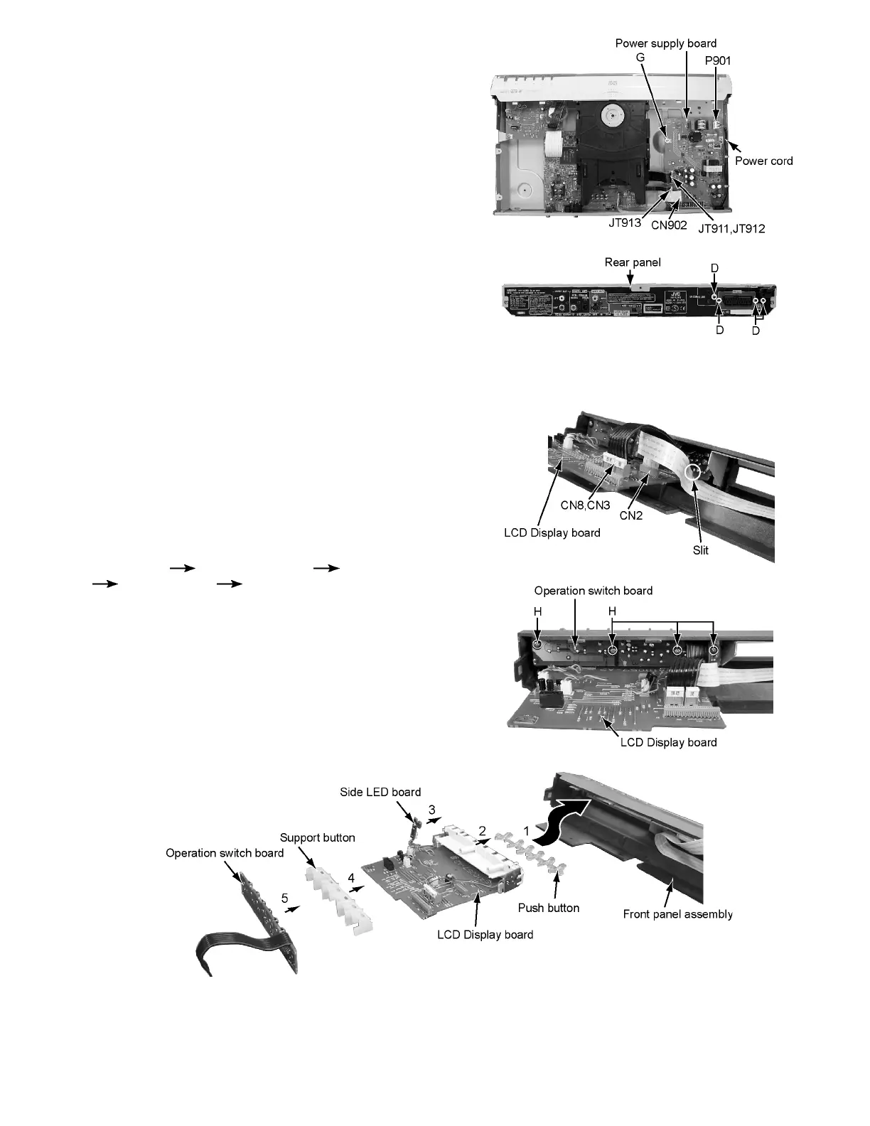
2.1.5 How to remove a power supply board
(See Figure 9 and 5)
• Please remove a top cover before removing a power supply
board.
(1) Extract flat wire from connector JT911, JT912, and JT913
on a power supply board.
(2) Extract card wire from connector CN902 on apower supply
board.
(3) Extract power supply cord from socket P901 on a power
supply board.
(4) Remove one screw G that attaches a power supply board
and four screws D that attaches a power supply board
from the rear side.
Fig.9
Fig.5
2.1.6 How to remove LCD display & operation switch
board
(See Figure 10, 11, and 12)
• Please remove a top cover and a front panel assembly before
removing LCD display & operation switch board.
(1) Extract card wire and flat wire from connector CN2, CN3,
and CN8 on LCD display board.
(2) Remove four screws H that attach an operation switch
board, and then operation switch board.
(3) Remove support button, LCD display board, and push but-
ton in this order.
• When the main part is assembled, parts must be assem-
bled in the following order:
Push button LCD display board Side LED board
Support button Operation switch board.
• After the operation switch board is attached to its place,
let a card wire through a slit on the operation switch
board, and then insert it in CN2. (See Figure 10.)
Fig.10
Fig.11
Fig.12

 Loading...