Document Number 481.093 Rev. A - 06/04
11
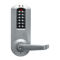
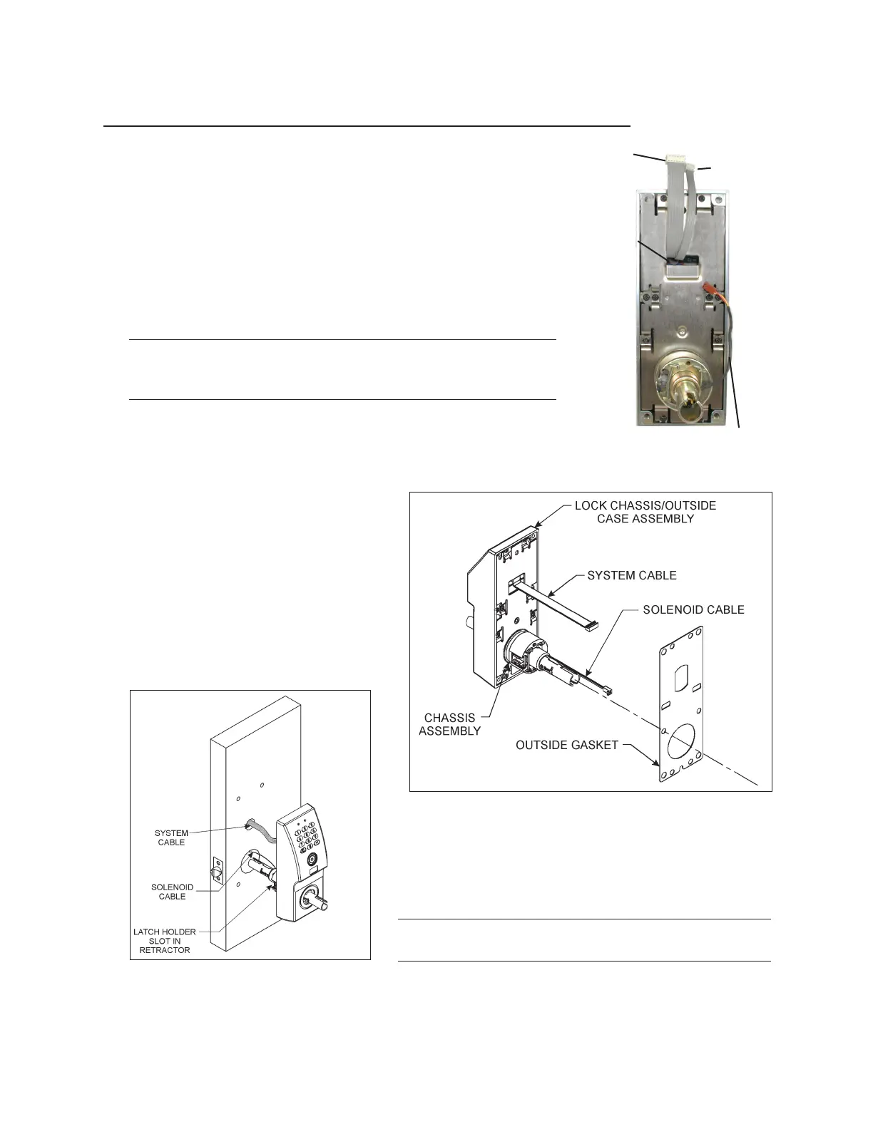
Install the Lock Chassis/Outside Case Assembly
If you are installing a Model 45xx lock or a PowerLever PROX
9000 lock, the outside case assembly includes a communication
cable that exits the outside case assembly at the same location
as the system cable (as shown in the photo.) The communication
cable is a 6-conductor ribbon cable that carries communication
signals from the RJ-12 connector on the outside case assembly
through the door to the system card.
1. If your lock includes outdoor gaskets (P/N 405054 - Inside
Gasket and P/N 405056 - Outside Gasket), you should at
this time install the Outside Gasket.
Warning: For outdoor applications, you must install the
gaskets. Otherwise, the product warranty will be voided.
Gaskets are not for use on fire doors.
Refer to Figure 9 and identify the Lock Chassis/Outside Case
Assembly and Outside Gasket (four holes at top and bottom).
Remove the paper backing sheet from the adhesive on the
Outside Gasket.
Slide the gasket down over the Chassis
Assembly and the cables, with the
adhesive side toward the Case Assem-
bly. Center gasket over Outside Case
Assembly. Ensure the gasket is cen-
tered in all directions so that an equal
amount of cover is visible around the
perimeter of the gasket. Once the
proper position of the gasket is verified,
press the gasket firmly into place.
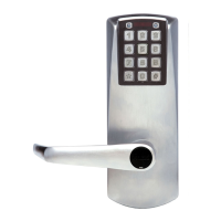
2.Refer to Figure 10. Make sure that the latch holder
slot in the chassis assembly faces the front edge of
the door.
Caution:Handle the electrical wiring harness with
care. Do not pinch the wires.
Figure 9 - Model 1550 shown
Exit 1/3 way
down from
top
Communication
Cable
System
Cable
Solenoid
Cable
Figure 10 - Model 45xx shown
Installation
 Loading...