Document Number 481.093 Rev. A - 06/04
1
INTRODUCTION
Lock Description
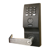
The PowerLever
®
Door Lock is an advanced design electronic lock that operates using inter-
nally-generated power, “PowerStar
TM
technology”, and includes a microprocessor and a cylindri-
cal lock mechanism. Installation of the following lock models is covered in this manual:
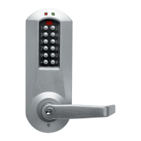
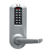
· PowerLever 1550
· PowerLever 4550/4560
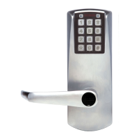
· PowerLever PROX 9000
Note: Various lock models will be shown throughout the Installation Guide.
The lock consists of the following major assemblies:
· Outside cover assembly - includes a keypad for entry of control data, a pair of LEDs (red
and green) for visual feedback, a beeper for audio feedback, and the outside lever with a
return of 1/2” (12.7mm) to the door (unassembled). Depending on which PowerLever lock
model you are installing, the cover assembly may also include a Smart Key* reader (Model
45xx only) or a PROX card reader, along with a communication port for a handheld PDA
(Personal Digital Assistant).
*
iButton
TM
memory device manufactured by Dallas Semiconductor.
· Inside cover hardware - includes system electronics and the inside lever with a return of
1/2” (12.7mm) to the door (unassembled).
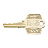
· Cylindrical lock hardware - includes a Grade 1 lock mechanism with free-wheeling system
and stainless steel retractor, a 6-pin standard key cylinder with tailpiece and two keys
(unless prepared for interchangeable core), a 9/16” (14.3mm) throw latchbolt with adjustable
bevel, and either a 2-3/4” (70mm) T-strike with box or a 4-7/8” (124mm) ASA strike, and a
screw pack.
Self-Power Operation
The PowerLever lock is designed to operate using internally-generated power. The self-con-
tained PowerStar generator is triggered by depressing the outside lever. Each 67-degree open
and 67-degree restore rotation of the lever constitutes a charging cycle. A door open operation
will require only one charging cycle if the period of door lever inactivity does not exceed a
weekend (approximately 65 hours) when operating at normal room temperature. Periods of non-
use beyond a weekend will require two charging cycles for a door open operation. One simulta-
neous flash of the green and red LEDs accompanied by a low volume beep indicates that the
lock is powered. Extended operations such as audit data downloads will require a charging cycle
approximately every 15 seconds. When lock power drops below a sufficient level for operation,
the lock will continually beep and flash the red LED, prompting the user to depress the outside
lever to provide additional power.
 Loading...