8
E-2 While holding the lock firmly against the out-
side of the door, use two round head thru-
bolts (D) to secure the inside reinforcing
plate (C). Finger tighten only.
E-3 Use a thin object A (screwdriver) to align tail-
piece (X) with the horizontal slot of the combi-
nation change assembly (G) (See Figure 5-3).
Attach the combination change assembly (G)
with two flat head thru-bolts (H). Finger tight-
en only (See Figure 5-2).
E-4 Securely tighten the two thru-bolts (D) to
reinforcing plate (C) (See Figure 5-2).
E-5 Position the cam on the inside rim deadlock-
ing (See Figure 5-4). Turn cam to the right
(clockwise) manually until it stops.
E-6 Mount the inside rim deadlocking latch (E) so
that tailpiece Y is engaged in the vertical posi-
tion. Secure evenly with four screws (F). (See
Figure 5-2).
E-7 Lightly push the combination change assem-
bly down and secure screws evenly (See
Figure 5-5).
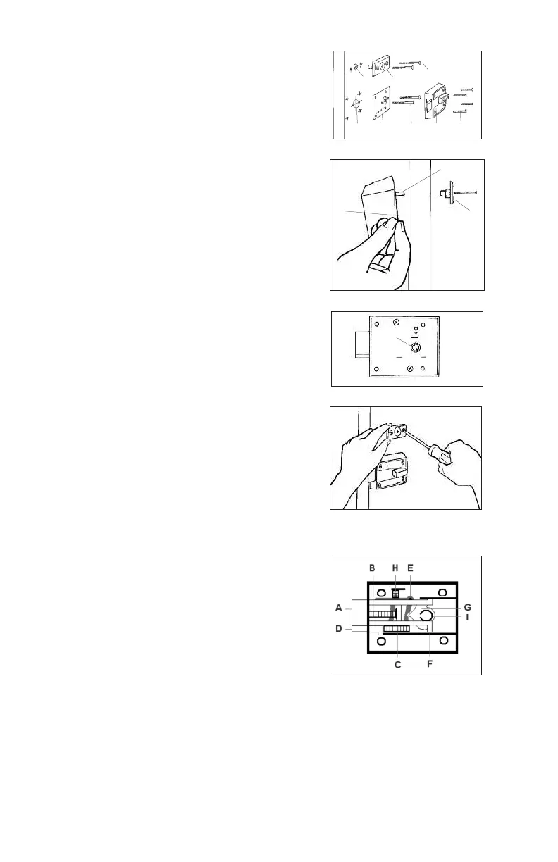
F. REVERSING THE LATCH
The model 7106 lock is packaged for an inward
opening door. For an outward opening door, the
latch must be reversed.
F-1 With the latch extended (A), remove the two
backplate screws from the underside of the
inside rim deadlocking latch. Remove the
backplate using a small flat blade screwdriver.
F-2 Carefully remove the latch spring (B) and
auxiliary latch spring (C) with a small flat
blade screwdriver.
F-3 Press the latch and auxiliary latch (D) into the
case to the stop position (See Figure 6-1).
F-4 Lift the auxiliary latch up and out. Reverse the auxiliary latch bevel and
place it back into the case. Hold the auxiliary latch down and slide it for-
ward so it will project
3
⁄8" (10 mm) beyond the case front and hold the aux-
iliary latch lever (E) out of the way.
A
5-3
5-5
X
5-4
A
G
6-1
5-2
A
C
D
E F
B
G
H