13
d. Place the strike back into this cutout and
trace the outline of the strike tongue (See
Figure 9-3).
e. Chisel out the frame so that the strike tongue
will be flush (approximately
5
⁄32").
f. Place the strike back into the cutout and
check that the large segment of the latch
enters the strike freely.
g. Secure the strike in the end with two
1
3
⁄4" (44 mm) screws and on the flat area
with three 1" (25 mm) screws provided.
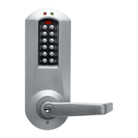
J. CHANGING THE COMBINATION
Important: The following steps must be
performed while the DOOR IS OPEN.
The factory pre-set combination is 2 and 4 pressed
simultaneously, then 3.
Read the instructions through once before
attempting to change the combination.
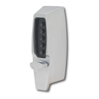
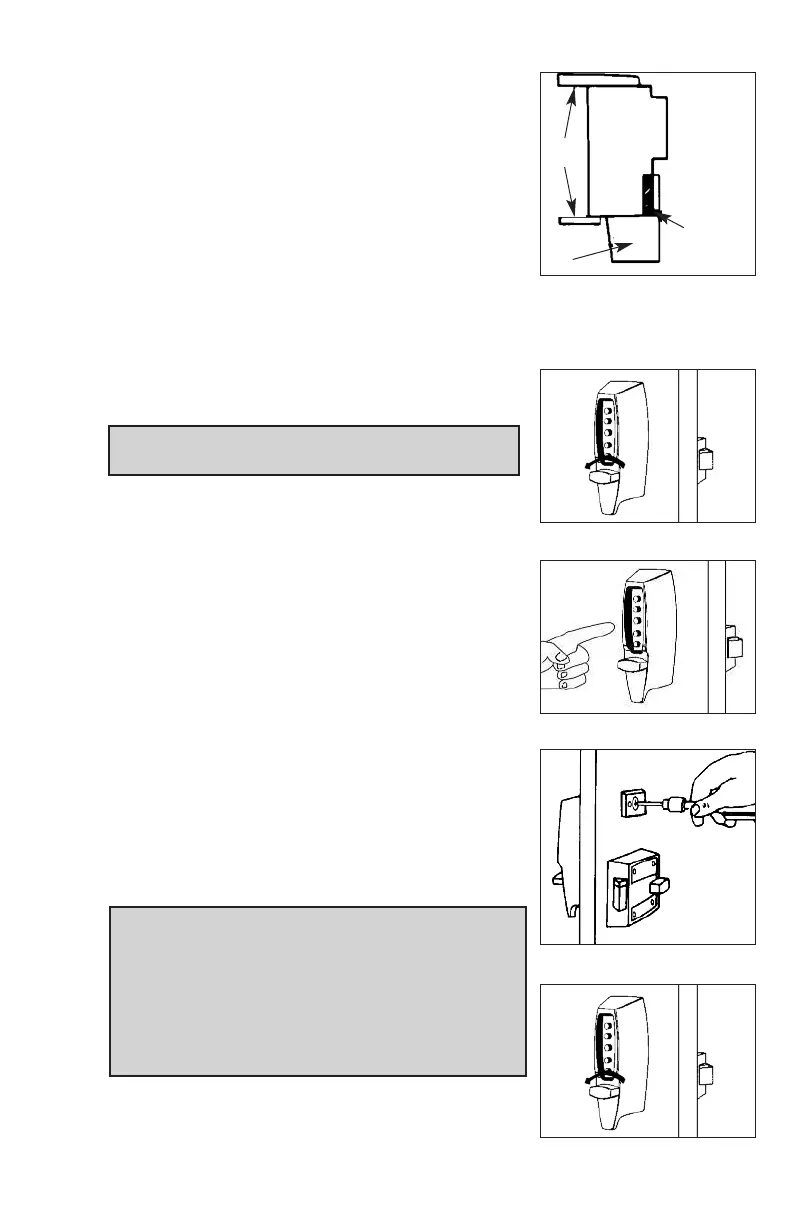
J-1 Turn the outside thumbturn to the left (counter-
clockwise) until it stops (See Figure 10-1) then
return it clockwise slowly to the horizontal posi-
tion and release.
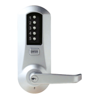
J-2 Enter the current combination (See Figure 10-2).
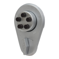
J-3 Insert a Phillips-head screwdriver into the cen-
tral piece of the combination change assem-
bly (See Figure 10-3). Gently rotate the screw-
driver to the right (clockwise) until it stops. A
slight click should be felt. DO NOT FORCE.
J-4 Remove the screwdriver from the combina-
tion change assembly.
Important: When removing the screwdriver, the
central piece must return to its initial position, if
not, set it back to its original position using the
screwdriver (See Figure 10-3). If the central
piece of the combination change assembly does
not return to its original position, the combination
will be cancelled and the lock will jam.
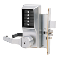
J-5 Turn the outside thumbturn left (counterclock-
wise) until it stops (See Figure 10-4) and return
it slowly clockwise to the horizontal position
and release.
9-3
C
hisel
out so that
strike tongue
will be flush
w
ith frame.
Door frame
Door
t
rim
B
ox
s
trike
10-3
10-1
10-4
10-2